When we say 'communication between UE and Network', we normally think about only signaling message (RRC or NAS message). When I say 'communication' in this case, it means 'control command exchange' between UE and network, not the data traffic.
In UMTS case, it is true that only RRC and NAS message functions as communication between UE and Network, but in LTE case there are several communication path at MAC layer. It implies that there are special MAC structure that carries special control information. These special MAC structure carrying the control information is called 'MAC CE', which means 'MAC Control Element'.
This special MAC structure is implemented as a special bit string in LCID field of MAC Header (Refer to LTE MAC page for the details of MAC header).
How LTE MAC header is encoded? What are different header elements in LTE MAC header?
LTE MAC PDU is a bit string but octet aligned (i.e multiple of 8 bits). A MAC PDU header consists of one or more subheaders. Each subheader corresponds to either a MAC SDU, MAC control element or padding.
MAC PDU header can have these six elements R/R/E/LCID/F/L. The last subheader in MAC PDU and subheaders for MAC control elements consists solely of four elements R/R/E/LCID. A MAC PDU subheader corresponding to padding consists of the four header fields R/R/E/LCID.
Here are some of the guidelines followed when multiple subheaders need to be present in a single MAC PDU
- MAC PDU subheaders have the same order as MAC SDUs, MAC control elements and padding
- MAC control elements always placed before MAC SDU.
- Padding occurs at the end of MAC PDU except when single byte or two bytes padding required. When single-byte or two-byte padding is required, one or two MAC PDU subheaders corresponding to padding are placed at the beginning of the MAC PDU before any other MAC PDU subheader.
A maximum of one MAC PDU can be transmitted per TB per UE. A maximum of one MCH MAC PDU can be transmitted per TTI.


MAC CE - Activation/Deactivation MAC Control Element
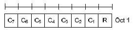
Refer to 36.321 6.1.3.8 Activation/Deactivation MAC Control Element if you want to have formal description. The field structure is as shown below.
< 36.321 Rel 10,11,12 - Figure 6.1.3.8-1: Activation/Deactivation MAC control element >
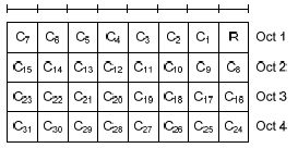
From Rel 13, UE Category 17 is added. Based Category 17, we can achieve 32 CC Carrier Aggregation and 25 Gbps. To support 32 CC (31 SCC), a new Activation/Deactivation MAC CE is added as shown below.
< 36.321 Rel 13 - Figure 6.1.3.8-2: Activation/Deactivation MAC control element of four octets >
Now the question is to figure out what does C1, C2, C3 etc mean ? Does it automatically mean C1 = SCC1, C2 = SCC2 etc ?
No.. the mapping between C1, C2,..,C7 and SCC1,SCC2,...,SCC7 is defined in RRC Connection Reconfig message. One example is as follows : (In example, sCellIndex-r10 for SCC1 (the first SCC) is set to be 2. It means C2 field in MAC CE is mapped to SCC1. Therefore, in this case 00000100 means that the first SCC shall be activated. This mean that absolution bit position in MAC CE does not specify whether it is for SCC1 or SCC2 etc. The meaning of each bit in MAC is indicated by RRC message. It means what is important is the matching between sCellIndex-r10 and MAC CE bit position. I hope following illustration would sound clearer to you.
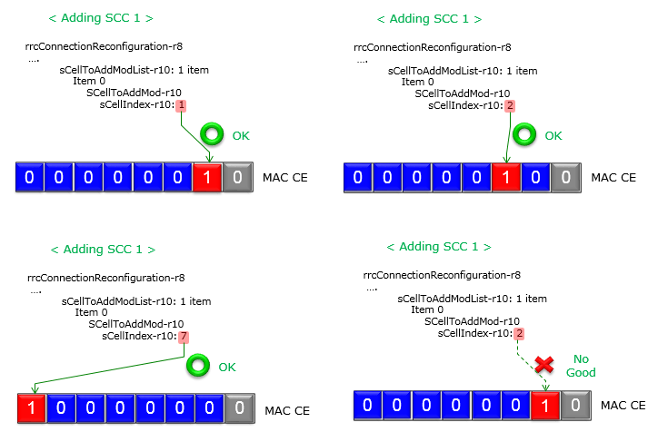
Following is an example of RRC Connection Reconfiguration message to add SCC1.
rrcConnectionReconfiguration-r8
radioResourceConfigDedicated
physicalConfigDedicated
pucch-ConfigDedicated-v1020
pucch-Format-r10: channelSelection-r10 (1)
channelSelection-r10
n1PUCCH-AN-CS-r10: setup (1)
setup
n1PUCCH-AN-CS-List-r10: 2 items
Item 0
N1PUCCH-AN-CS-r10: 4 items
Item 0
N1PUCCH-AN-CS-r10 item: 361
Item 1
N1PUCCH-AN-CS-r10 item: 362
Item 2
N1PUCCH-AN-CS-r10 item: 363
Item 3
N1PUCCH-AN-CS-r10 item: 364
Item 1
N1PUCCH-AN-CS-r10: 4 items
Item 0
N1PUCCH-AN-CS-r10 item: 365
Item 1
N1PUCCH-AN-CS-r10 item: 366
Item 2
N1PUCCH-AN-CS-r10 item: 367
Item 3
N1PUCCH-AN-CS-r10 item: 368
nonCriticalExtension
nonCriticalExtension
nonCriticalExtension
sCellToAddModList-r10: 1 item
Item 0
SCellToAddMod-r10
sCellIndex-r10: 2
cellIdentification-r10
physCellId-r10: 1
dl-CarrierFreq-r10: 3100
radioResourceConfigCommonSCell-r10
nonUL-Configuration-r10
dl-Bandwidth-r10: n50 (3)
antennaInfoCommon-r10
antennaPortsCount: an1 (0)
phich-Config-r10
phich-Duration: normal (0)
phich-Resource: one (2)
pdsch-ConfigCommon-r10
referenceSignalPower: 18dBm
p-b: 0
radioResourceConfigDedicatedSCell-r10
physicalConfigDedicatedSCell-r10
nonUL-Configuration-r10
antennaInfo-r10
transmissionMode-r10: tm1 (0)
ue-TransmitAntennaSelection: release (0)
release: NULL
pdsch-ConfigDedicated-r10
p-a: dB0 (4)
ul-Configuration-r10
cqi-ReportConfigSCell-r10
nomPDSCH-RS-EPRE-Offset-r10: 0dB (0)
cqi-ReportPeriodicSCell-r10: release (0)
release: NULL
No comments:
Post a Comment
If You have any concern you are free to message/comment me.