Thanks www.sharetechnote.com LTE TDD Overview | |||||||||||||||||||||||||||||||||||||||||||||||||||||||||||||||||||||||||||||||||||||||||||||||||||||||||||||||||||||||
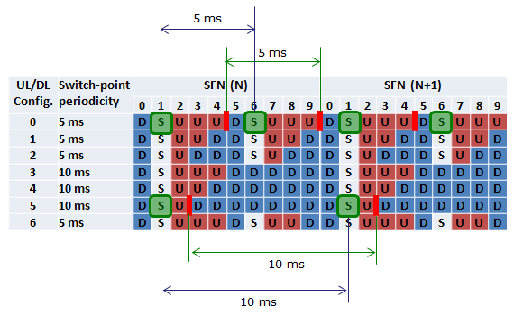
< Subframe(UL/DL) Configuration >
< Special Subframe Length >
For the examples of TDD resource grids for each Subframe DL/UL Configuration and Special Subframe Configuration, see Frame Structure Frame Type 2 Overview section.
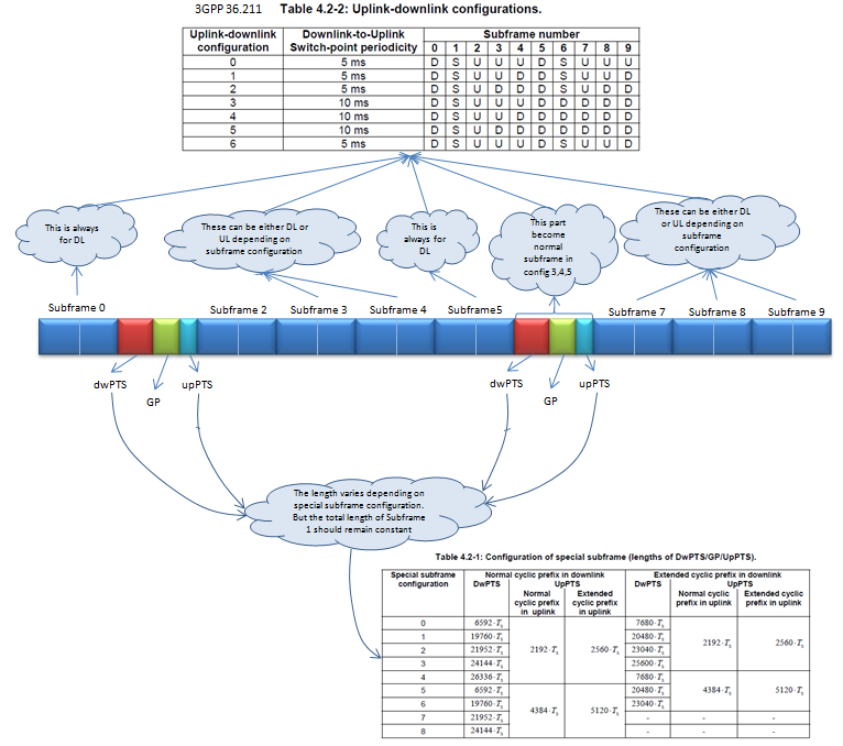
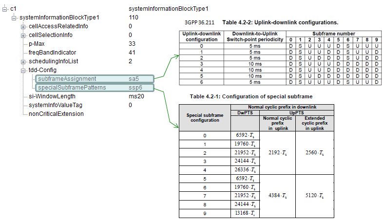
Now the question comes, who decides the sequence of these subframes. That has been defined by 3GPP with the name TDD Frame Configurations. There are fixed patterns of these configurations and network operator has to choose out of these defined patters. There are total 7 TDD configurations as shown below:  And there comes a Special subframe which comes when there is transition from downlink subframe to uplink subframe. It has three parts – DwPTS(Downlink Pilot Time Slot),GP (Guard Period) and UpPTS (Uplink Pilot Time Slot) and all of these have configurable lengths, which depends upon Special subframe configuration. Special subframe configuration as shown below: 
How Special subframe configuration impact Cell Size? In TDD , there are 9 special subframe configuration, each have different number of OFDM symbols for DwPTS,GP and UpPTS. Special subframe guard period impact the size of cell, it represent how much propagation delay it can compensate. Longer guard period can compensate more propagation delay result a longer cell size.  
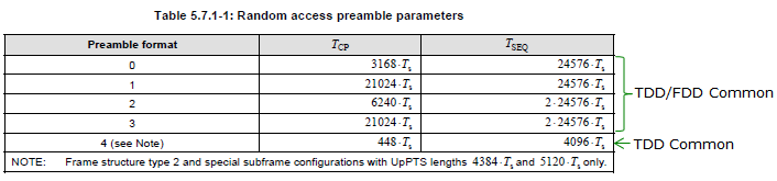
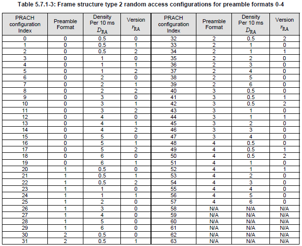
Refer to 36.211 5.7 Physical random access channel for the details.
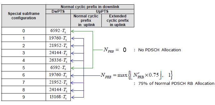
< RB Allocation on Special Subframe >
Refer to 36.213 7.1.7 Modulation order and transport block size determination for the details.
In case of FDD, it is pretty simple and obvious for UE to transmit HARQ ACK or NACK. UE start preparing the response as soon as it completes the decoding PDSCH and transmit it 4 ms (4 TTI) later. But in TDD, UE cannot transmit the response in such a fixed timing as in FDD. It has to wait until it gets the next chance for UL transmission and the next chance will be different depending on UL/DL configuration. Even when UE gets the chance to transmit the UL, it is may not always possible to transmit all the necessary response. For example, if UE gets too many DL subframe before the UL subframe, it will be difficult to transmit the all the reply in the UL transmission because PUCCH space is not big enough to accomodate all the HARQ ACK/NACK. So they came out with very complicated/confusing table as shown below to define HARQ response to cope with this kind of situation. In this section, I will explain how to interpret this table and figure out the exact HARQ response timing for each UL/DL configuration.
< ACK/NACK from UE for PDSCH >
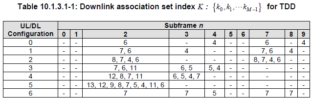
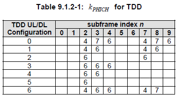
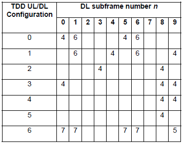
Following table shows the Ack/Nack Transmission Timing from UE for the PDSCH it recieved.
Problem is how to interpret this table. Following shows how to interpret each raw of the table.
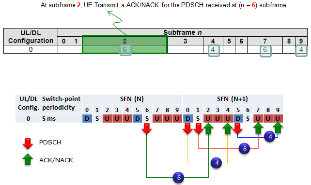
Case 1 : UL/DL Configuration 0
In case of UL/DL Configuration 0, Ack/Nack response timing for the PDSCH that is received by UE is transmitted according to the following rule.
How do you interpret this table and DL/UL correlation ?
It says
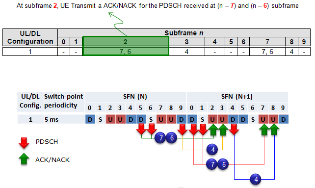
Case 2 : UL/DL Configuration 1
In case of UL/DL Configuration 1, Ack/Nack response timing for the PDSCH that is received by UE is transmitted according to the following rule.
How do you interpret this table and DL/UL correlation ?
It says
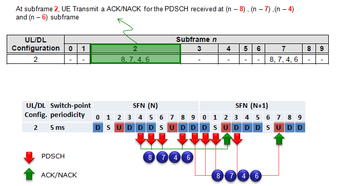
Case 3 : UL/DL Configuration 2
In case of UL/DL Configuration 2, Ack/Nack response timing for the PDSCH that is received by UE is transmitted according to the following rule.
How do you interpret this table and DL/UL correlation ?
It says
Please try to do the same analysis for the remaining UL/DL Configuration on your own. It would be the best way for you to understand the meaning of the table clearly.
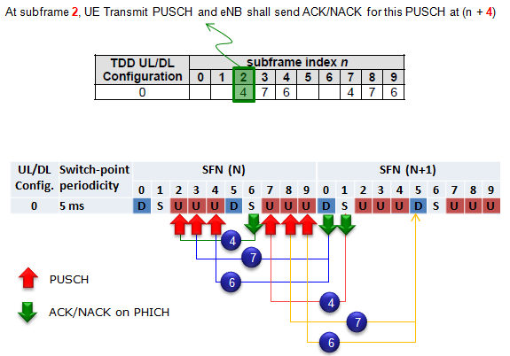
< ACK/NACK from eNB for PUSCH >
Case 1 : UL/DL Configuration 0
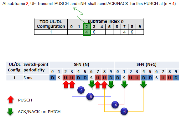
Case 2 : UL/DL Configuration 1
The Time delay between SR(Scheduling Request) and DCI 0 is not clearly specified in 3GPP specification. So basically, NW can send DCI 0 in any available DL subframe after reception of SR, but depending on the eNodeB and Test Equipment some minimum time interval may be required.
If UE recieves DCI 0 at subframe n, it should send PUSCH at subframe n + k where k is defined as follow. I will post some graphical explanation for this table later. Until then, give it a try on your own to understand this table.
36-213 V9.3.0 (2010-10) Table 8-2 k for TDD configurations 0-6
What was your first impression about all the Ack-Nack report mechanism described above ? My first impression was "So complicated !" and "So.. So.. So.. confusing". Unfortunately.. there is more serious problem than the 'confusing things'. It is about troubleshooting issues.
Let's assume that you are using DL/UL Configuration 2. and suppose UE sent a NACK at Subframe 2. How did you know whether the NACK is for PDSCH at subframe 4 or 5 or 6 or 8 ? (As you know, in FDD.. the answer is so simple since the ACK/NACK from the UE is always for the PDSCH that it received 4 subframe before. If it is FDD, the answer is supposed to be 'it is for PDSCH received at subframe 8 in previous SFN), but in TDD case it is different as you may guess.
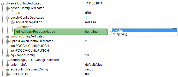
As described above, in TDD LTE ibe subframe can transmit ACK/NACK for multiple subframe as shown below. In the following figure as an example, UE send ACK/NACK for 4 PDSCHs in subframe 2. What should eNB do if the subframe 2 send NACK ? Does it have to retransmit the whole 4 PDSCHs ? or transmit only PDSCH which is NACKed ?
The answer to the question gets different depending on tdd-AckNackFeedbackMode setting in RRC message (e.g, RRC Connection Setup or RRC Connection Reconfiguration). If it is set to be 'bundling', eNB should retransmit all the PDSCH. If it is sent to be 'multiplexing', eNB should retransmit the only PDSCH which is NACKed.
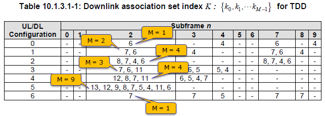
You would notice the variable 'M' in many of the statement above. M is defined to be "the number of elements in the set K defined in Table 10.1.3.1-1". Following examples would give you clearer idea on the meaning of M.
System Information Variation
Q. In TDD, why special sub-frame is used for switching Downlink (DL) to Uplink (UL) . Why not for UL to DL ? What’s the reason Please clarify. There are 2 versions of the answer , some people will get satisfied with version 1, others with version 2. Both are correct, but that’s how we all learn , what convinces us. Version 1: For TDD, in the Downlink , due to path distance DL signal can be delayed. Due to path distance , path delay is created. Delay can cause collision between UL and DL signals. The guard period provides enough time for DL delayed signal to arrive due to path distance, and also gives enough opportunity for (User Equipment)UE to receive UL timing advance command from the Base station. Follow up Question. Why special sub-frame only in DL to UL, why not from UL to DL ? UE always transmit in UL after receiving grant from the BS. BS can advance or retard the UL timing command as needed. Once DL signal is received completely then UE can send command /signal in return with respective timing ( UE cannot transmit on its own before receiving a complete response from the DL) . So we need a guard period for DL to UL switching, to avoid collisions. Whereas in case of UL to DL switching there is no need of Guard period, as eNodeB has timing advance feature plus there will be minimum chance of collision in UL to DL case.  In DL to UL switching , a Guard Period is needed , ” To avoid the time advanced UL to collide with the delayed DL” Version 2: A simple answer is in TDD because there is no duplex Frequency and all management must be done on the same path, then UE should first receive info about up-link(most important one is Time scheduling ). Therefore, Downlink should always be done before Uplink in TDD mode. If you have anything else to add , feel free to write it in the comments below.
| |||||||||||||||||||||||||||||||||||||||||||||||||||||||||||||||||||||||||||||||||||||||||||||||||||||||||||||||||||||||
Tweet4technology: It’s about LTE, 5G-NR and new Technology, 3GPP has dubbed 5G's new air interface 5G NR (New Radio).
No comments:
Post a Comment
If You have any concern you are free to message/comment me.