PDCCH Resource Allocation
One PDCCH is carried by multiple number of consecutive CCEs. How many CCEs are necessary to carry one PDCCH ? It depends on the format of the PDCCH. The relationship between PDCCH format and the number CCE required to carry the PDCCH is as follows :
- PDCCH Format 0 : Requires 1 CCE = Aggregation Level 1 (2^PDCCH Format = 2^0 = 1)
- PDCCH Format 1 : Requires 2 CCE = Aggregation Level 2 (2^PDCCH Format = 2^1 = 2)
- PDCCH Format 2 : Requires 4 CCE = Aggregation Level 4 (2^PDCCH Format = 2^2 = 4)
- PDCCH Format 3 : Requires 8 CCE = Aggregation Level 8 (2^PDCCH Format = 2^3 = 8)
The number of consecutive CCEs required to carry one PDCCH is called "Aggregation Level'. TS 36.211 Table 6.8.1.1 shows these relations.
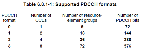
Now let's look into a little bit deeper and see how 'Number of PDCCH bits' is derived for each PDCCH
Number of PDCCH bits for PDCCH Format 0 = 1 (CCE) x 9 (REG/CCE) x 4 (RE/REG) x 2 (bits/RE, QPSK) = 72
Number of PDCCH bits for PDCCH Format 1 = 2 (CCE) x 9 (REG/CCE) x 4 (RE/REG) x 2 (bits/RE, QPSK) = 144
Number of PDCCH bits for PDCCH Format 2 = 4 (CCE) x 9 (REG/CCE) x 4 (RE/REG) x 2 (bits/RE, QPSK) = 288
Number of PDCCH bits for PDCCH Format 3 = 8 (CCE) x 9 (REG/CCE) x 4 (RE/REG) x 2 (bits/RE, QPSK) = 576
What does this mean in practical sense ? It means that even the same DCI with exactly same bit length, the number of physical channel bits gets different depending on which PDCCH format it is carried by. It means the Code Rate of PDCCH varies depending on which PDCCH format is used.
For example, if we use DCI Format 2A (I don’t remember the exact bit length… but it would be around 40 bits)
Case 1 : If we use Aggregation Level = 1
i) After Channel Coding, the bit length would be about 120
ii) After Rate Matching, it should be 72 (1 CCE)
Case 2 : If we use Aggregation Level = 2
i) After Channel Coding, the bit length would be about 120
ii) After Rate Matching, it should be 144 (2 CCE)
Case 3 : If we use Aggregation Level = 4
i) After Channel Coding, the bit length would be about 120
ii) After Rate Matching, it should be 288 (4 CCE)
Case 4 : If we use Aggregation Level = 8
i) After Channel Coding, the bit length would be about 120
ii) After Rate Matching, it should be 576 (8 CCE)
- LTE Throughput Optimization: Part 1 – PDCCH Capacity Enhancement
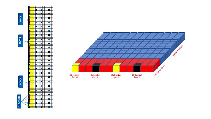
There are many ways to optimize LTE throughput and I will try to cover all of them. The LTE throughput optimization procedure described in this article requires PDCCH enhancements. The general idea is that the LTE subframe is made up of PDCCH and PDSCH as explained in my article LTE Frame Structure Made Simple. The PDCCH is used for control information while the PDSCH carries the actual data. So, if the PDCCH resources are reduced then that means that the PDSCH resources can increase which in turn means that there will be more data per subframe. Since, each subframe is 1 ms in LTE so it actually means there will be more bits per millisecond which is the definition of throughput.
Firstly, let’s try to understand PDCCH itself and how it works. A PDCCH is used to give scheduling allocations to the UE on the PDSCH or PUSCH. For example, if the UE has data in the PDSCH, it needs to know where the data is located. The PDCCH will tell the UE that the data it is looking for is located at this location on PDSCH. This means that if the UE is unable to decode PDCCH then the UE cannot read the PDSCH in that subframe and consistent decoding failures of PDCCH lead to RLF (Radio Link Failure) due to N310. Hence, the decoding of PDCCH is extremely important and that is why it uses a special structure which is different than other channels.
PDCCH is made up of CCEs (Control Channel Elements) and each CCE is made up of 36 REs (Resource Elements). PDCCH further uses a concept of aggregation layers which is a group of CCEs. There are 4 aggregation layers in the normal PDCCH
– Aggregation layer 1 : This uses 1 CCE and it is the smallest block so it is only used in very good radio conditions.
– Aggregation layer 2 : This uses 2 CCEs and it is usually the most common aggregation layer in normal radio conditions.
– Aggregation layer 4 : This uses 4 CCEs and it is a robust allocation. It can be used for signalling and control information allocations.
– Aggregation layer 8 : This uses 8 CCEs and it is the most robust allocation. Users in very bad radio conditions are allocated with this layer or it can be used for control information.
Let’s have a look at how many users can be scheduled by PDCCH in a subframe. This depends on the number of CCEs that the subframe can handle which in turn depends on many factors. Let’s have a look at a couple of examples
– Consider a 10 MHz channel using 2×2 MIMO (2 CRS ports). The PDCCH can span over 3 symbols at maximum and may use 1 symbol at minimum. The number of RBs in a 10 MHz channel is 50 and this means that a symbol can hold a maximum of 600 REs. However, in the first symbol, we have 2 RS per RB for each antenna port. This means that there will be a total of 4 RS per RB in the first symbol and since there are 50 RBs so total RS count will be 4*50 =200 REs. Moreover, there is a PCFICH control channel that spans over 4 REGs or 16 REs. Then there are PHICH groups and each PHICH group occupies 3 REGs or 12 REs. If the Ng parameter is 1 then there will be 7 PHICH groups in 10 MHz channel so the total PHICH overhead will be 12*7=84.
Number of REs in one symbol : 50*12 = 600
Overhead in Symbol 1 = 200 RS + 16 REs of PCFICH + 84 REs of PHICH = 300 REs
Overhead in symbol 2 = 0 REs
Overhead in symbol 3 = 0 REs
Total REs available for PDCCH (REs available in 3 symbols) = 1800 – 300 = 1500 REs
Total CCEs available for PDCCH = 1500 REs / 36 = 41 CCEs
This means that if all the users are in very good radio conditions, then there can be 41 users scheduled in 1 TTI (1 ms) with 3 PDCCH symbols. However, this does not happen because the radio conditions of the users are usually distributed and there are common allocations like TPC (transmit power control) commands which are usually at a bigger aggregation layer since it carries allocations for multiple users. So, if there is one TPC command which takes 8 CCEs then around 33 CCEs are remaining. These CCEs will be divided between downlink and uplink data allocations. Usually, downlink data is more so most of the allocations are taken by downlink. Consider that the users are in good conditions and require 2 CCEs each then there can be 16 users in each TTI (16*2 =32 CCEs) with 3 PDCCH symbols.
Now that the PDCCH structure is out of the way, let’s have a look at the optimization procedures for PDCCH.
As described above, the PDCCH symbol usage can go upto 3. Each subframe has 14 symbols so if PDCCH uses 3 symbols, then the PDSCH will only be able to use 11 symbols. If the PDCCH symbol number is reduced to 1, then the PDSCH symbol count can increase to 13 which is around 15% improvement in throughput or capacity. However, if we change the PDCCH symbol count to 1 then that means that the available PDCCH CCEs will reduce to 8 (300/36=8) since the first symbol has 300 REs available and other 300 REs are used by RS, PCFICH and PHICH. And if we need to transmit a TPC command then it will utilize all the CCEs and we cannot transmit any data allocations.
In order to tackle this, most of the vendors have introduced a dynamic algorithm that changes the PDCCH symbol count with respect to the requirement of the users. If there is data for 6 users and a TPC command, it will use 2 symbols for PDCCH and if there is only 1 user that needs to be scheduled, it will reduce the PDCCH symbol count to 1. Activating this algorithm is the first step to ensure optimum balance between PDCCH and PDSCH.

The PDCCH allocation is mostly based on a BLER target accompanied by a CQI input. If the UE is showing a good CQI, the eNB will allocate a good aggregation layer. For example, the UE reported CQI index 12 which shows that it is in good radio conditions then the eNB will allocate it aggregation layer 2 which uses 2 CCEs. Now, consider that the UE moves away and eNB experiences BLER so the eNB will increase the aggregation layer to 4 to provide more robustness to the PDCCH. However, there is another way to increase the robustness and that is to increase the PDCCH power. Vendors have dynamic power features for PDCCH and if such a feature is used, it will increase the PDCCH power with the same aggregation layer to increase the robustness. This means that the UE will stay with the same aggregation layer using 2 CCEs and since it did not expand to 4 CCEs so there was a gain of 2CCEs or 72 REs which might prevent the eNB to increase the PDCCH symbol from 1 to 2 resulting in an extra symbol for PDSCH.

Another approach is to tune the PDCCH BLER target. If the BLER target is slightly increased, then the eNB will use the same PDCCH aggregation layer for longer and this will reduce expansion of PDCCH resulting in a lower CCE utilization and reduced overhead. However, if the BLER target is increased excessively, the UEs might fail to decode the PDCCH resulting in retransmissions.
Another dimension is the coding rate for the PDCCH aggregation layers. If there is more number of bits in a particular PDCCH allocation, then it might exceed the upper limit of the Aggregation Layer 1. So, the eNB will have to expand to the bigger aggregation layer. This happens because the eNB has a threshold for maximum coding rate per aggregation layer. However, if the maximum coding rate threshold is increased, the eNB will be able to send more bits within the same aggregation layer. This would reduce the transitions to higher aggregation layers and might reduce the overhead. As an example, a transmit diversity allocation uses lesser number of PDCCH bits compared to a Open Loop Spatial Multiplexing (TM3) allocation. So, if a network has Transmit Diversity and it moves to Open Loop Spatial Multiplexing, an increase in aggregation layer will be observed. Similarly, if the network shifts from Open Loop to Closed Loop, another increase in aggregation layer will be observed as Closed Loop MIMO allocations take more number of bits on PDCCH compared to Open Loop MIMO allocations. This can be mitigated by increasing the maximum coding rate threshold for the PDCCH. But increasing it reduces the robustness of the PDCCH and therefore, a balance must be maintained.
The gain of the PDCCH optimization is directly proportional to the utilization and load on the PDCCH. If the network is lightly loaded then most of the time PDCCH will only be using 1 symbol and since that is the minimum number of symbols allocated to PDCCH so there will be no gain with any of the above mentioned changes. If the network is congested and PDCCH is consistently using 3 symbols then such measures can help in reducing the symbols to 2 which can expand the PDSCH or data capacity. However, in all the cases, special care must be taken that this does not increase decoding failures excessively.
In case of any queries or feedback, please drop a comment below and I would love to respond and help.
No of CCE Calculation: FDD 20 MHz, 4 CRS., CFI =3
No of RBs = 100
Total No of REs = 3 * 1200 = 3600
No of REs carrying Reference Signal = 4 * 100 ( 1st symbol) + 4 * 100 ( 2nd symbol) = 800 ( Since 4 CRS)
No of PCFICH Symbol ( Always in Symbol 0) = 16 REs
No of PHFICH Symbol ( Always in Symbol 0) = 156 REs (For Ng =1, No of PHICH groups = 13, Size of 1 PHICH group = 12 REs, then total no of REs for PHICH is 13 * 12 =156 REs )
No of PDCCH REs = 3600 – 800 – 16 – 156 = 2628 REs
We know that 1 CCE = 9 REG and 1 REG = 4REs
1 CCE = 9 * 4 REs = 36 REs
No of CCEs = 2628/36 = 73 CCEs
After knowing PDCCH, I personally feel that it is the heart of LTE . So we should try to understand it completely that:-
What information it carries?
Where it carries the information?
And for whom it carries the information?
PDCCH carries a message called DCI ( Downlink Control Information ) which includes resource assignments for a UE or group of UE's. EnodeB can transmit many DCI's or PDCCH's in a subframe. Actually enodeB need to send a lot of parameters to the UE for its operation but there may be the cases that some information is not required for a particular UE.
For Example:- Some UE does not support MIMO ( Multiple Input Multiple Output ), so for that UE there is no need to send the MIMO related parameters because they will increase the signalling overhead.
There comes in the picture the different formats for sending the information which are called DCI formats. Even we would not like to have so many formats because they will increase the complexity. So to cover the most useful cases we have following DCI formats:-
DCI format 0 is used for uplink allocation, all other formats are used for allocating the resources in downlink.
- Format 0 for transmission of resources to UE for sending their uplink data
- Format 1 for downlink allocation of resources for Single Input Multiple Output (SIMO)case
- Format 1A for downlink allocation of resources for SIMO operation or allocating a dedicated preample signature to a UE for random access
- Format 1B for transmission control information of Multiple Input Multiple Output (MIMO) rank 1 based compact resource assignment
- Format 1C for very compact transmission of PDSCH assignment
- Format 1D same as format1B with additional information of power offset
- Format 2 and Format2A for transmission of DL-SCH allocation for closed and open loop MIMO operation, respectively
- Format 3 and format3A for transmission of TPC command for an uplink channel
Allocation of resources happens in terms of CCE ( Control Channel Elements ).
1 CCE = 9 continuous REG's ( Resource element Group )
1 REG = 4 RE ( Resource Element )
CCE allocation for PDCCH :-
PDCCH uses the resources present in first n OFDM symbols where
n - Value present in PCFICH ( Number of OFDM symbols )
So the number of CCE's present to transmit the control information will be variable depending on the
- PCFICH value
- Bandwidth of the system from 1.4 Mhz to 20 Mhz.
- Number of antenna ports present which in turn will effect the reference signals present.
Lets take an example for the number of CCE available calculation:-
Step -1 :- We need to find the total number of RE's available in first n OFDM symbols where n is coming from the value of PCFICH.
Suppose n = 3
Total RE's = n * x * y
n - PCFICH value
x - number of subcarriers in 1 RB
y - total number of RB's considering 10 Mhz bandwidth
Total RE's = 3 * 12 * 50 = 1800 RE's
RE's for PDCCH = Total RE's -
Number of RE's used for reference signals -
Number of RE's used in PHICH -
Number of RE's used in PCFICH
CCE's available for PDCCH = RE's for PDCCH /36
as 1 CCE = 36 RE's.
eNodeB uses the PDCCH for sending the control information for a particular UE or a group of UE's. It means eNodeB uses the PDCCH for some broadcast information also which is common for all the UE's. So to make that process easier eNodeB divided its CCE's into two parts which we call them as search space:
- Common search space :- It consists of CCE's which are used for sending the control information which is common for all the UE's .Maximum number of CCE present in common search space is 16. For Example:- Common search space CCE's are used by eNodeB for sending the control information of SIB's which is common for all UE's.
- UE specific search space :- CCE's belonging to UE specific space are used for sending the control information for a particular UE only. That means information present on UE specific CCE's can only be decoded by a specific UE.
Lets suppose there are total 100 CCE's eNodeB has for sending the control information combining both common space and UE specific search space.

Suppose enodeB has used 85th CCE number for a UE named ravan for sending his control information.
Now how the Ravan will come to know which CCE he needs to decode for getting his information. Either he needs to scan all 100 CCE's one by one and try to find the information. This procedure will consume a lot of battery power for the UE. So to simplify this process,
eNodeB has fixed some indexes for a particulat UE based on the rnti and the subframe, so now ravan needs to find his control information only on those specific CCE indexes.
How eNodeB calculate those CCE indexes for a UE:-
First we should be familiar with some terms used in this procedure:-
- Aggregation Level :- It is defined as number of CCE's used for sending a control information. Its values can be 1,2,4 and 8. Suppose for UE named ravan eNodeB is using some DCI format whose size comes out to be 90 bits after applying the code rate.
- Code rate:- It is mainly a physical layer funda for sending the information in a redundant way such that chances of UE successfully decoding it gets increased.
1 CCE = 36 RE's
1 RE = 2 bits ( For QPSK modulation)
4 bits( For 16 QAM )
6 bits ( For 64 QAM)
- PDCCH candidates :- Number of CCE indexes serached by a UE in a subframe for a particular search space. These values are fixed by spec 36213 as mentioned in table :-
Search space | Number of PDCCH candidates | ||
Type | Aggregation level | Size [in CCEs] | |
UE-specific | 1 | 6 | 6 |
2 | 12 | 6 | |
4 | 8 | 2 | |
8 | 16 | 2 | |
Common | 4 | 16 | 4 |
8 | 16 | 2 | |
- PDCCH Format :- There are four PDCCH formats available as shown below

The set of indexes searched by a UE depends on a formula given by spec as:-


L - Aggregation level
A PDCCH consisting of n consecutive CCE's may only start on a CCE index fulfilling
i mod n = 0
where i = CCE number
For Example:-
eNodeB wants to allocate PDCCH for some UE or group of UE's on aggregation level 4 ( Means 4 CCE's are required), Then it can only allocate CCE's starting with indexes which satisfies
(CCE index) mod 4 = 0
How to find CCE indexes on common search space:-
As shown in table eNodeB uses only aggregation level 4 and 8 for the allocation in common search space .
Maximum number of CCE's present in common search space is fixed as 16. If the total number of CCE's available in the system are less than 16 for any bandwidth then all the CCE's will be present in common search space.
The position of Common search space CCE's is always fixed starting from the first CCE index.

As we know that starting CCE's are common search space CCE's , so in the diagram green color CCE's are common search space CCE's from index 0 to 15.
Suppose eNodeB wants to allocate CCE's for SIB on common search space for aggregation level 4
And we know that it should satisfy the formula
1. (CCE Index ) mod 4 = 0,
2. And from the table above , the number of PDCCH candidates ( starting CCE indexes) for aggregation level 4 in common space can be 4.
By meeting the above two conditions 4 indexes will be supported by aggregation level 4 in common space as
CCE index 0 - will contain consecutive CCE's from 0 to 3
CCE index 4 - will contain consecutive CCE's from 4 to 7
CCE index 8 - will contain consecutive CCE's from 8 - 11
CCE index 12 - will contain consecutive CCE's from 12 -15
Similarly if eNodeB wants to allocate with aggregation level 8, then possible indexes meeting the two conditions will be
CCE index 0 - will contain consecutive CCE's from 0 to 7
CCE index 8 - will contain consecutive CCE's from 8 to 15
As we know that UE does the blind PDCCH decoding , means it does not have any idea about the aggregation level or DCI format used by the eNodeB. So a UE in common space needs to make
(4 try in aggregation level 4 + 2 try in aggregation level 8 ) * DCI format supported for common space
only small sizes DCI formats are supported in common search space as 0/1A/3/3A/ and 1C
so if enodeB supports 1A and 1C DCI formats, so UE needs to do 12 tries maximum to decode its PDCCH information.
According to the formulas in spec 36213 as:-
The set of indexes searched by a UE in a subframe is:-
A = 39827
D = 65537
Lets take an example:-
Subframe number = 0
Aggregation level = 1
We know from the table above that for aggregation level 1, number of PDCCH canditates ( CCE indexes) can be 6.
Yk = (A * Yk-1 ) mod D
k = subframe number
As k = 0
Yk-1 = RNTI value for that UE, lets suppose its 100.
Yk = (39827 * 100) mod 65537
= 50480
CCE index =
L = aggregation level
i = 0 to (Aggregation Level - 1)
Ncce = Number of CCE's available for PDCCH ( suppose 100)
m' = 0 to ( Number of PDCCH canditates -1 )
CCE index = 1 { (50480 + 0 ) mod (100/1)} + 0
= 80
So first CCE index for aggregation level 1 for this UE in subframe 0 will be 80.
Lets calculate next CCE index for the same UE in the same subframe.
Yk value changes with the subframe only so withion the subframe same value will be used.
CCE index = 1 { ( 50480 + 1 ) mod ( 100 /1 )} + 0
= 81
Similarly you can calculate the remaining CCE indices for this UE in the current subframe
Lets try to find the CCE indices for subframe 1 now with aggregation level 2:-
As we know that Yk value changes with subframe
Yk = (A * Yk-1) mod D
= (39827 * 50480) mod 65537
= 53948
Yk-1 will be the value calculated for subframe 0
For aggregation level two also
m' will be 0 to 5 as number of PDCCH candidates are 6 for aggregation level 2
CCE index = 2 {(53948 + 0) mod (100/2)} + 0
=96
As in Aggregation level 2, two CCE's will be allocated for the same PDCCh candidate
Second CCE will be = 2{(53948 +0)mod (100/2)} + 1
= 97
So first CCE index for this UE in subframe 1 for aggregation level 2 will be 96. This PDCCH candidate will contain 2 CCE's with indexes 96 and 97.
In similar ways UE can find the CCE indexes available in all subframes for the different aggregation levels.
CCE Allocation Examples:-

- If terminal A is using the CCE's 16 to 23 then terminal B cannot be addressed on Aggregation level 4 as the CCE's are already blocked by terminal A.
- We can also notice that, CCE's 24- 31 belongs to both of the UE's PDCCH candidate set for aggregation level 8. That means overlap can also happen but eNodeB can actually use it for one terminal either A or B.
- For point 1 like case, common search space CCE's can be used to resolve the contention. This is also another inportant use of common search space.
- It is also clear that first 16 CCE's are used for common search space in both aggregation level 4 and 8.
How EnodeB decides which DCI Format to use:-
It is decided by enodeB on the basis of transmission mode and the RNTI type used for that particular PDCCH.
RNTI types:-
- SI- RNTI :- Used for transmission of system information messages.
- RA-RNTI :- Used for PRACH responses.
- P-RNTI :- Used for the paging messages
- C-RNTI :- Used for the transmission to a specific UE after RACH.
- T-CRNTI :- Mainly used during Rach.
I am consolidating that information from spec in a easy way to understand.
Usually all the common information gets scheduled in common search space with the CRC scrambled with all RNTI's except CRNTI. We use DCI format 1A or 1C irrespective of Transmission mode.
Please find the table for the mapping :-

- PDCCH order is also transmitted with DCI format 1A.
Blind Decoding of PDCCH by UE :-
UE does the blind decoding because:-
- UE does not have idea about the CCE's used by PDCCH
- UE does not know the aggregation level used by eNodeB
- UE do not have idea about the DCI format used by eNodeB

- ULSCH PDCCH or DCI format 0 which is used for uplink grant is scrambled with Antenna selection mask . It is done to intimidate the UE about the antenna port it needs to use for its transmission.
- PDCCH shall be transmitted on the same set of antenna ports as PBCH.
- PDCCH is transmitted in starting OFDM symbols to save battery at UE.
- In one subframe or 1 ms , multiple DCI's needs to be send by eNodeB for sending the data to different UE's.
- For 1 UE, eNodeB can send multiple DCI's if it needs to send data and give uplink grant in the same tick.
- UE needs to keep on decoding CCE's if it is expecting more than one DCI's.
No comments:
Post a Comment
If You have any concern you are free to message/comment me.