>> SIB2->
{rach_ConfigCommon
{numberOfRA_Preambles = n52
sizeOfRA_PreamblesGroupA = n44
PowerRampingParameters {PowerRampingStep
= dB2, PreambleTransMax = n5, mac_ContentionResolutionTimer = sf48}
bcch_Config
pcch_Config
pdsch_ConfigCommon{
ReferenceSignalPower
= -10
p_b = 0}
pusch_ConfigCommon {GroupHoppingEnabled}
pucch_ConfigCommon{deltaPUCCH_Shift = ds2, nRB_CQI,
nCS_AN}
UplinkPowerControlCommon{p0_NominalPUSCH =
-75, p0_NominalPUCCH = -96, Alpha = al08}
Prachconfigindex
>> SIB1 ->
message c1 : systemInformationBlockType1 :
cellAccessRelatedInfo
plmn-IdentityList
cellReservedForOperatorUse notReserved
trackingAreaCode '00010110 00000000'B,
cellIdentity '00000000 00110010 00010011 0000'B,
cellBarred notBarred,
intraFreqReselection allowed,
cellSelectionInfo
q-RxLevMin -64
freqBandIndicator 5,
schedulingInfoList
si-Periodicity rf16,
sib-MappingInfo
si-Periodicity rf32,
sibType3
si-Periodicity rf128,
sib-MappingInfo
si-Periodicity rf128,
sib-MappingInfo
sibType15-v1130
si-WindowLength ms10,
systemInfoValueTag 1
>>
What is Functionality & RACH process?.
>> RAPID in
RACH response and Back of indicator.
Answer:
Backoff Indicator is a special MAC subheader that carries
the parameter indicating the time delay between a PRACH and the next PRACH.
Example:
if the BI field value is 10,
Backoff Parameter value is 320 ms. this means UE can send PRACH any time in
between 0 and 320 ms from now.
There is another case where UE needs to retry PRACH. It is
the case where UE received RAR from the network, but the RAPID is not for it
(It means that RAR is not for some other UE). In this case, it is highly
probable that a Backoff Indicator value is transmitted with RAR to control the
PRACH retransmission timing.
>>
Contention Resolution
- UEs synchronize with the downlink channel by decoding the PSS and SSS signal. The UEs are synchronized to the downlink frames after completing this procedure.
- The three UEs initiate the random access procedure at exactly the same time. Two of them (UE-A and UE-B) happen to pick the same preamble. This results in a resulting in a collision. UE-C picks a distinct preamble so it succeeds in the random access procedure.
- Contention between UE-A and UE-B is resolved in UE-A’s favor. UE-A proceeds with the RRC connection.
- UE-B times out and retries the random access procedure.
What is MAC-ContentionResolutionTimer?
The timer which states the number of consecutive subframe/subframes during which MAC entity will monitor the PDCCH after the Msg3 is transmitted. (3GPP TS 36.321 version 13.3.0 Release 13)
The UE will start mac-Contention resolution timer from the immediate subframe after transmitting Msg3.
As UE is waiting for the contention resolution which is through PDCCH reception on C-RNTI (in connected mode), the UE should be monitoring PDCCH. So that the time duration in which mac-Contention resolution timer is running, is also considered as Active Time.
Which timer is started after msg3 is transmitted?
Following two timers are started Once, msg3 is transmitted:
1. T300 : Transmission of RRCconnectionRequest
2. Contention Resolution Timer: broadcasted in SIB2. If the UE doesn't receive msg4 (Contention Resolution message) within this timer, then it go back to msg1 i.e. transmitting RAP. If there is a HARQ NACK for msg3 (RRCconnectionRequest) and it has to be re-transmitted then this Contention Resolution Timer will be re-started.
What if two UE attempted RA with the same RA preamble sequence on the same RA channel?
If multiple UEs attempt RA with the same RA preamble sequence on the same RA channel (RA-RNTI) then the eNodeB will receive msg1 from multiple UEs.
The eNodeB will detect the preamble transmission and estimate the uplink transmission time of the UEs.
The eNodeB will derive the RA-RNTI from the timeslot number in which the preamble is received. Using this information the eNodeB will transmit the RA Response on the DL-SCH channel. The message carries the timing and uplink resource allocation information for Preamble. The message also contains the backoff indicator MAC header for which controls the backoff duration in the event of a random access procedure.
All UEs receive the message as they were expecting the message on the same RA-RNTI. Then UE’s saves the Temporary C-RNTI from the MAC data for Preamble. After applying the correction, the UE is synchronized in the return direction and can transmit data bursts to the eNodeB. It is likely that its transmission will not be received at the eNodeB as it is transmitting with a timing advance that was not intended for the UE.
The eNodeB receives Msg3 (RRC Connection Request) from both the UEs. Here, the eNodeB will send msg4 (Contention Resolution) with MAC CRI (Contention Resolution Identity) to both the UEs. This CRI will carry a reflection of the RRC Connection Request as generated by one of the UEs. The MAC layer of the UE will match the CRI (as received from msg4) with the CRI embedded in the RRC Connection Request. If it matches, then the UE will proceed to decode RRC Connection Setup and the other UE will back off and return to Msg1, i.e. start the RA procedure again.
Type of contention Resolution process?
Contention Resolution process is again of two types:
1. MAC based Contention Resolution
=> C-RNTI on PDCCH
=> uses the DCCH logical channel
=> used in HO scenarios
==> here the rule: if the UE have a valid C-RNTI and UE is going for RA procedure then it can say that it will be a MAC based Contention Resolution procedure
2. L1 based Contention Resolution
=> CRI (Contention Resolution Identity) on DL-SCH based
=> Contention Resolution is addressed to T-CRNTI
=> uses CCCH logical channel
=> here the rule: if the UE don't have a valid C-RNTI and UE is going for RA procedure then it can say that it will be L1 based Contention Resolution procedure.
Why the macCRT timer is required?
This timer is to check if the eNB has sent the Contention Resolution Identity MAC CE in response to msg3 to complete the contention resolution procedure (for contention based mechanism). If no such message from eNB during this timer, then the new RACH procedure happened.
How does ContentionResolutionTimer work in NB-IOT?
If the UE is an NB-IoT UE, the MAC entity shall use the macContentionResolutionTimer for the corresponding enhanced coverage level if it exists.
Which msg body in you can find macContentionResolutionTimer ?
Sib 2
What happened when macContentionResolutionTimer is expire?
When the macContentionResolutionTimer is expire then tow think happened.
⦁ discard the Temporary C-RNTI
⦁ Consider the Contention Resolution not successful.
What is the start and end activity of macContentionResolutionTimer?
Once Msg3 is transmitted, the MAC entity will start mac-ContentionResolutionTimer and restart mac-ContentionResolutionTimer at each HARQ retransmission.
Regardless of the possible occurrence of a measurement gap or Sidelink Discovery Gap for Reception, monitor the PDCCH until mac-ContentionResolutionTimer expires or is stopped.
If the MAC PDU is successfully decoded then mac-ContentionResolutionTimer stop.
Source:https://www.eventhelix.com/lte/random-access-procedure/lte-random-access-procedure.pdf
Same PRACH preamble from multiple UE reaches the NW at the
same time. This kind of PRACH collision is called "Contention" and
the RACH process that allows this type of "Contention" is called
"Contention based" RACH Process.
i) UE --> NW
: RACH Preamble (RA-RNTI, indication for L2/L3 message size)
ii) UE <-- NW
: Random Access Response (Timing Advance, T_C-RNTI, UL grant for L2/L3 message)
iii) UE -->
NW : L2/L3 message
iv) Message for
early contention resolution
>>
Exactly when & where a UE transmit RACH?
>>
Through PRACH config index, it is determined by SIB2.
Answer:
The set of 64 preamble sequences within a cell are divided
into two groups:
This group of sequences can be further divided into 2
sub-groups:
- ·
'Group A' sequences selected by the UE when the
uplink data quantity to be sent is relatively small, or when the UE is in poor coverage.
- ·
'Group B' sequences selected by the UE when the
uplink data quantity to be sent is relatively large, and the UE is in good coverage.
The division of PRACH sequences is illustrated in Figure
167. The number of 'Group B'
preamble sequences can be set to 0 by configuring the value of 'Size of RA
Preambles in Group A' to equal the value of 'Number of RA Preambles'.
The maximum allowed value for 'Number of RA Preambles' is 64 so it is possible to use all of the
sequences for contention based random access, and not reserve any sequences for the non-contention based procedure.
Group A sequences
are indexed from 0 to 'Size of RA
Preambles in Group A'- 1, where the 'Size
of RA Preambles in Group A' parameter ranges from 4 to 60 and is
broadcast in SIB2.
Group B sequences
are indexed from 'Size of RA Preambles
in Group A' to 'Number of RA
Preambles'- 1, where the 'Number of
RA Preambles' parameter ranges from 4
to 64 and is broadcast in SIB2.
The UE selects a group B sequence if both of the following
conditions are satisfied:
- Message Size > Group A Message Size Threshold AND
- Path Loss< P1UAX- Target Rx Power- Preamble to Msg Delta-
Group B Offset
Where, ‘Group A
Message Size Threshold’, ‘Target Rx Power’, ‘Preamble to Msg Delta’ and ‘Group
B Offset’ are broadcast in SIB2.
Once the UE has selected either Group A or Group B, a
preamble is selected at random from within that group.
If Msg3 has not yet been transmitted, the UE shall:
- if Random Access Preambles group B exists and if the potential message size
(data available for transmission plus MAC header and, where required, MAC control elements)
is greater than messageSizeGroupA threshold &&
if pathloss < PCMAX–preambleInitialReceivedTargetPower–deltaPreambleMsg3 – messagePowerOffsetGroupB,
then:
- select the Random Access Preambles group B;
else:
select the Random Access Preambles group A.
>> Preamble format?
>>How to determine
which preamble format to use PRACH configindex determine which preamble format
will use.
Answer:
How UE know which
Preamble format it has to use when it generate PRACH and transmit ?
It is determined by
following table. As you see, PRACH Configuration Index determines the Preamble
Format to be used.
For example, if PRACH
Configuration Index is 10 as shown in the following example, the preamble
format 0 is used.
Who determines
PRACH Configuration index ?'. The answer is 'eNB determines it via
prach-Configindex IE in SIB2'. Refer to prach-ConfigIndex section for the
details.
>> Why multiple preamble
format? Especially why we need various PRACH format with different length of
time?
Let's look into
T_SEQ (length of Sequence). You see format 0 and format 1 is made up
of single copies of PRACH converted in time domain. Format 2 and 3 is made
up of two copies of PRACH sequence concatenated. What would be the advantage
that format 2,3 have over format 1,2. I
think the longer T_SEQ would help decoding PRACH under noised condition because
it provide longer correlation window to detect PRACH.
Now let's look
at T_CP part. you would notice format 1 and 3 has much longer T_CP
comparing to format 0 and 2. Longer CP would give you better tolerance in
fading environment and reducing ISI even in highly fading environment.
Different time and
length (Tseq) would be help decoding PRACH under noised condition b/c it
provide longer correlation window detect PRACH.
Note 1 : T_CP
(in ms) = T_CP(in Ts) x 0.03255 x 1/1000,
where
0.03225 is one Ts in us, 1/1000 is used to convert the unit from 'us' to 'ms'
Note 2 :
T_SEQ (in ms) = T_SEQ(in Ts) x 0.03255 x 1/1000,
where
0.03225 is one Ts in us, 1/1000 is used to convert the unit from 'us' to 'ms'
Note 3 : Guard
Time (in ms) = Number of Subframe - Total Length
Note 4 : Cell
Radius is roughly the distance that the electromatic wave can travel during the
guard time and devided by 2.
In
case of free space(in vacumm) it is roughly is 300 (km/ms) x Guard Time (ms) /
2.
It is simple.
Network knows when UE will send the RACH even before UE sends it because
Network tells UE when the UE is supposed to transmit the RACH.
(If UE fails to
decode properly the network information about the RACH, Network will fail to
detect it even though UE sends RACH).
Following section will describe network information on RACH.
>>
When do I have to retry? (What should be the time delay between the previous
transmission and the next transmission?)
>>
Do I have to retransmit the PRACH with the same power as previous one? Or try
with a little bit higher power? If I have to try with a little bit higher
power, how much power do I have to increase?
Answer: PowerRampingStep
Example, powerRampingStep = dB2. It means UE has to increase
PRACH power by 2 dB every time it retries.
>>
If I keep failing to receive RACH response, how many time I have to retry? Do I
have to retry until the battery runs out ?
Answer: preambleTransMax
= n6. It means UE retries PRACH retransmit only 6 times and then give up.
Once the Random Access Preamble is transmitted and
regardless of the possible occurrence of a measurement gap, the UE shall
monitor the PDCCH for Random Access Response(s) identified by the RA-RNTI
defined below, in the RA Response window which starts at the subframe that
contains the end of the preamble transmission [7] plus three subframes and has
length ra-ResponseWindowSize subframes.
It means the earliest time when the network can transmit the
RACH response is 3 subframe later from the end of RACH Preamble.
>> Paging/CSFB
Answer:
The main purpose of a Paging message is to page UEs in
RRC_IDLE mode for a mobile terminated call. Also the Paging message can be used
to inform UEs, in RRC_IDLE as well as
in RRC_CONNECTED modes Paging messages originating from the
MME to notify the terminal about incoming connection requests., is used in the
RRC_IDLE state described further below)
when the terminal is not connected to a particular cell.
Indication of system-information update is another use of the #Paging
mechanism, as is public warning systems.
>> RLF on which
Layer?? Who sent reestablishment??
Answer: Radio
Link Failure is "Physical Layer(especially low PHY) break" and in
most case this failure is unintentional. UE may assume that Radio Link is broken in the following situation.
- The measured RSRP is too low (under a certain
limit)
- It failed to decode PDCCH due to power signal
quality (e.g, low RSRP, RSRQ)
- It failed to decode PDSCH due to power signal
quality (e.g, low RSRP, RSRQ)
Triggering Point of RLF.
- Upon indication from RLC that the maximum number
of re transmissions has been reached
- Upon expiry of Timer T310 (this timer is started
when physical layer problems are detected i.e. upon receiving N310 consecutive
out-of-sync indications from lower layers)
- Upon random access problem indication from MAC
while neither T300, T301, T304 nor T311 is running Based on poor channel conditions, Max retransmission of SR
can reach when UE sends SRs dsrMaxretrans times. it is set upto 64.
- The UE tries to do RACH attempt after SR failure, as it loses
the sync with the NW. If the RACH failure happens then RLF is declared and UE
does re-establishment.
>> Back of
Indicator: Backoff Indicator is a special MAC subheader that carries the
parameter indicating the time delay between a PRACH and the next PRACH.
The UE exits the random access procedure if the maximum
number of transmissions has been reached. The maximum allowed number of
transmissions is broadcast within SIB2,
The eNodeB can increase the value of the back-off timer by
attaching an E/TIRIR/BI subheader to a Random Access Response (RAR) message on the
PDSCH. This may be done during periods of congestion. The backoff timer is signaled as a Backoff Indicator (BI)
which has a length of 4 bits.
>> If ARQ is implemented on RLC Layer the why
HARQ is implemented at MAC Layer.
Ans: If Packet
are delaying on MAC so not be retransmit on RLC Layer so HARQ is implemented on
MAC Layer. If MacHARQTx=8 Then it transmit upto 8. If it will cross 8
then it will transmit from RLC Layer.
>> Difference
between TX diversity and MIMO??
Answer:
TX diversity:
- TX diversity improve Reliability it does not improve data
rate or throughput.
- Signal should be reached without any loss.
- Same data is received by multiple antenna simultaneously.
- This form of LTE MIMO scheme utilizes the transmission of
the same information stream from multiple antennas.
- This mode provides an improvement in signal
quality at reception and does not improve the data rate.
MIMO (2*2 4*4 8*8)
- Gain in Throughput
- No gain in Reliability
- UE experiencing good coverage (with high signal to noise
ratios) can take advantage of the spatial multiplexing gain and can receive multiple parallel streams of data. The maximum number of parallel streams is
given by the minimum of the number of transmit and receive antenna.
- For example, 2x2 MIMO, 4x2 MIMO and 2x4 MIMO are all capable
of transferring a maximum of 2 parallel streams of data. Maximizing throughput also relies upon having uncorrelated propagation
paths between the transmit and receive antenna.
- UE in poor coverage (with a low signal to noise ratios) can
take advantage of the diversity gain to help improve their signal to noise ratio. The magnitude of the diversity gain is dependent upon the number of
receive antenna and the level of correlation between each of the propagation paths, i.e. the gain is maximized for a large number of receive
antenna and uncorrelated propagation paths.
- This dependency upon channel conditions means that MIMO is used
to transfer multiple parallel streams of data in good coverage conditions to maximize throughput, and is used to transfer a single stream of
data in poor coverage conditions to maximize the diversity gain.
>> Difference
between Close loop spatial multiplexing and Open loop spatial multiplexing?
Answer:
Open loop spatial:
- Transmissions are configured with minimal feedback from the UE.
- Open loop spatial multiplexing involves feedback from the UE
in terms of Rank Indication (RI) and Channel Quality Indicator (CQI).
- It is categorised as 'open loop' because the UE is not required to provide feedback
in terms of a Precoding Matrix Indicator (PMI)
Close loop spatial:
- Transmissions
are configured with detailed feedback from the UE.
- Closed loop spatial multiplexing involves feedback from the
UE in terms of RI, CQI and PMI.
- The UE selects a PMI to maximize the signal to noise ratio at its receiver. Applying the set of precoding weights at
the eNodeB represents a form of maximum ratio combining at the transmitter.
- MIMO can transfer either 1 or 2 codewords during each 1 ms
subframe. A codeword is a transport block which has been processed by the Physical layer in terms of CRC addition, channel coding and rate matching
Layer Mapping- maps
the modulated symbols belonging to either 1 or 2 codewords onto a number of'
layers' where the number of layers is less than or equal to the number of antenna ports.
Precoding- Applies coding to the
'layers' of modulated symbols prior to mapping onto Resource Elements and
subsequent
OFDMA signal generation.
- When 2 codewords are transferred, they do not need to be of
equal size. CQI reporting, link adaptation and HARQ run independently for each codeword. In some cases, a single HARQ acknowledgement is used for
multiple codewords due to the constraints in signaling capacity, e.g. ACK/NACK multiplexing for TDD.
- 4x4 MIMO cannot transfer 4 codewords during a 1 ms subframe,
but 2 large codewords can be scheduled and subsequently divided into 4 sections. 8x8 MIMO can transfer 2 even larger codewords which can be
divided into 8 sections. A maximum of 2 codewords has been standardised to optimize the trade-off between receiver processing and
performance, and to reduce the signaling requirement in terms of CQI and HARQ acknowledgement reporting.
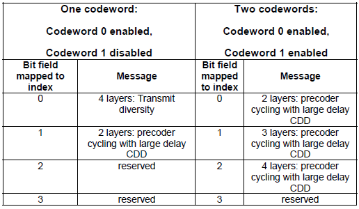
Example:
4x4 MIMO can transmit
1 to 4 layers from 4 antenna ports
- Using 1 layer allows 1 codeword to be
transferred during each 1 ms subframe and is applicable to when RF channel
conditions are relatively poor, or when the eNodeB does not have much data to transfer.
- Using 4 layers allows 2 large codewords to be
transferred during each 1 ms subframe and is applicable to when RF channel conditions are good. Transferring 2 large codewords across 4 layers allows peak
connection throughputs to be increased by a factor of 4. An intermediate number of layers can be used
when the channel conditions do not allow the maximum number of layers, i.e.
- the correlation between some of the propagation paths between the transmit antenna
and receive antenna is too high.
The majority of transmission modes allow the eNodeB to
switch between transmission techniques without RRC signaling, e.g. transmission mode 3 allows the eNodeB to dynamically switch between transmit
diversity and open loop spatial multiplexing.
Transmission mode 3: provides support for open loop spatial multiplexing. Transmission mode 3 allows
the eNodeB to dynamically switch between transmit diversity and open loop spatial multiplexing without
having to use RRC signaling to complete a reconfiguration. The eNodeB switches
between these two transmission schemes according to the channel conditions.
DCI format 2A is used to allocate resources for open loop spatial multiplexing. This DCI allows
information to be signaled for either 1 or 2 transport blocks. It also allows precoding information to be included for 4x4 open loop
spatial multiplexing. This precoding information signals
the number of layers being used rather than the set of precoding weights. The
UE is required to provide feedback in terms of both CQI and Rank Indication (RI). The RI provides the eNodeB with a recommended number of layers. In this
case, spatial multiplexing is categorized as open loop because the UE
does not need to provide feedback in terms of a Precoding Matrix Indicator
(PMI).
Transmission mode 4 : Provides
support for closed loop spatial multiplexing. Transmission mode 4 allows the
eNodeB to dynamically switch between transmit diversity and closed loop spatial multiplexing without
having to use RRC signaling to complete a reconfiguration. The eNodeB switches
between these two transmission schemes according to the channel conditions.
DCI format 2 is used to allocate resources for closed loop spatial multiplexing. This DCI
allows information to be signaled for either 1 or 2 transport blocks. It also allows precoding information to be included. The UE is required
to provide feedback in terms of CQI, RI and a Precoding Matrix Indicator (PMI). The PMI provides the eNodeB with a
recommended set of precoding weights.
>>MU-MIMO:
In mode 5 (Multi-user MIMO), different UEs are receiving downlink data from
different antenna. Transmission mode 5
provides support for multi-user MIMO but limits the transmission to a single layer
per UE (only a single transport block can be sent to each UE during each subframe). Transmission mode
5 allows the eNodeB to dynamically switch between transmit diversity and multi-user MIMO without having to use RRC signaling
to complete a reconfiguration. DCI format 1D is used to allocate resources for multi-user MIMO. Multi-user MIMO can transfer
2 transport blocks during a subframe and addresses those 2 transport blocks to 2 different UE. The UE is required to provide
feedback in terms of CQI and PMI. The PMI can be used by the eNodeB when selecting the precoding weights for multi-user MIMO. The UE is not
required to report a Rank Indication (RI) because the multi-user MIMO transmission is always single layer.
>> Transmission
mode 9 : provides support for single user beamforming with up to 8x8 MIMO. In
terms of multi-user MIMO, transmission mode 9 is similar to transmission mode 8, i.e. 2 UE can simultaneously benefit
from dual layer beamforming, or 4 UE can simultaneously benefit from single layer beamforming. When configured for
single user beamforming antenna ports 7 to 14 are used.
When configured for multi-user MIMO antenna ports 7 and 8 are used in combination
with 2 scrambling identities. The UE reports CQI by default, and the eNodeB can request the UE to also report Precoding Matrix
Indicators (PMI) and Rank Indicators (RI). Transmission mode 9 also uses Precoder Type Indications (PTI) to signal the type
of content within subsequent PMI reports. DCI
format 2C was introduced within the release 10 version of the 3GPP
specifications for the purposes of transmission mode 9.
>> Beam forming – A
unique way of transmission , where the different side lobes of antennas are
used to direct the signal in a particular direction This will
reduce interference, and increase capacity as the particular UE will have a
beam formed in their particular direction. In this a single code
word is
transmitted over a single spatial layer. A dedicated reference signal is used
for an additional port.
>> The
UE uses Uplink Control Information (UCI) to provide the eNodeB with feedback.
It includes:
Channel State Information (CSI)
{
Channel Quality Indicator
Precoding Matrix Indicator
Precoding Type Indicator
Rank Indicators (RI)
}
Scheduling Requests (SR)
HARQ Acknowledgements
>> CSI: Channel State Information (CSI)
includes the following 4 components: CQI,PMI, PTI, RI
>> A Scheduling Request (SR) is a single
bit flag used to request PUSCH resources from the eNodeB. Scheduling Requests are always
transferred using the PUCCH. UE are provided with configuration information regarding Scheduling Requests
within an RRC Connection Setup, RRC Connection Reconfiguration or RRC Connection
Re-establishment message. The Scheduling Request Configuration Index
can be signaled with a value between 0 and 157. After
transmitting the first SR on PUCCH, if the UE doesn’t receive uplink resources
from the eNodeB, then based on the periodicity, the UE re-sends SR on PUCCH.
This process continues till UE transmits SR for dsr-TransMaxnumber of times on
PUCCH if the UE doesn’t receive uplink resources from the eNodeB. After
transmitting SR for maximum (dsr-TransMax) number of times, the UE releases SR resources (frequency as
well as time), initiates random access procedure and cancels all pending
(triggered) SRs.
>> CFI(Control
Format Indicator)
Answer: It tell
how many OFDM symbol is used for carrying PDCCH at each subframe. CFI Carried
by specific physical channel PCFICH, carry only CFI without any other
information.
CFI is made by 31 bit data pattern.
If CFI->1 for a subframe means One symbol at subframe is
used for PDCCH allocation. <0110110110111011011011…>
If CFI->2 it means 2 symbol are used for PDCCH
allocation.
PHICH = Location of PCFICH, Where it will decode PCFICH. It
will go with MIB.
PCFICH = PCFICH carry CFI -> Control format indicator.
CFI indicate how many OFDM symbol will use to carry PDCCH at each subframe.
PDCCH= Its indicate which type of data is going on PDSCH.
PDSCH=
>> DCI and UCI
Format:
DCI-> Control information for DL and UCI-> Control
information of UL.
>> Code rate??
Answer: The UE may skip decoding a transport block in
an initial transmission if the effective channel code rate is higher than
0.930, where the effective channel code rate is defined as the number of
downlink information bits (including CRC bits)divided by the number of physical
channel bits on PDSCH. If the UE skips decoding, the physical layer indicates
to higher layer that the transport block is not successfully decoded.
>> Transport
Block size
Answer: In short,
the transport block size itself is calculated in MAC/L2 and not in physical
layer.
The MAC has to first decide on the modulation scheme that
can be scheduled to the user and then check the physical resource grid for
availability of the resource blocks. From this step the MAC can decide upon the
modulation and coding scheme index (I_MCS) and then decide upon the
number of resource blocks (N_PRB), that can be allocated to the user. After
this step the transport block size index (I_TBS) is derived from the look up
table as specified in the LTE PHY specification 36.213 sec 7.1.7.1 for downlink
and sec 8.6.1 for uplink.
So after knowing the I_TBS and N_PRB, there
shall be a table look up as specified in LTE PHY specification 36.213, section
7.1.7.2.1, which will determine the transport block size for the current
subframe for the user.
>> Collision
between CSI and Positive SR in same subframe or periodic CSI report and an
HARQ-ACK in a same subframe??
Answer:
If the UE is not configured for simultaneous PUSCH and PUCCH
transmission or, if the UE is configured for simultaneous PUSCH and PUCCH
transmission and not transmitting PUSCH, in case of collision between CSI and
positive SR in a same subframe, CSI is dropped.
It means .. if there is a case where UE needs to send both SR and
CQI, SR transmission has higher priority and CQI gets dropped.
ll. In case of collision between CSI and positive SR in a
same subframe, CSI is drop
In case of collision between a periodic CSI report and an
HARQ-ACK in a same subframe without PUSCH and the UE is configured with a
single serving cell, the periodic CSI report is multiplexed with HARQ-ACK on
PUCCH if the parameter simultaneousAckNackAndCQI provided by higher layers is
set TRUE, otherwise the CSI is dropped.
In case of collision between a periodic CSI and an HARQ-ACK
in a same subframe with PUSCH, the periodic CSI is multiplexed with the
HARQ-ACK in the PUSCH transmission in that subframe if the UE is not configured
by higher layers simultaneous PUCCH and PUSCH transmissions. Otherwise, if the
UE is configured by higher layers simultaneous PUCCH and PUSCH transmissions,
the HARQ-ACK is transmitted in the PUCCH and the periodic CSI in transmitted in
the PUSCH.
>> Is there any
specific events in LTE that support only interfrequency and intrafrequency HO?
Answer: I can be
possible that only one event can support both inter and intra frequency HO.
This depends on eNodeB software implements.
Suppose an UE wants to perform inter frequency HO but is
does not support a5 event measurement and support a3 event measurement
then eNodeB can configure a3 event for inter frequency HO
with intra frequency HO.
>> What is difference between event A3 and A4 in LTE from
handover purpose.
Answer:
A3 event - UE
measures both serving and neighbor cell.
A3:
Yes, UE measure both Serving and neighbor cell but with the
following condition:
The LTE Event A3 is triggered when a neighboring cell becomes better than the
serving cell by an offset. The offset can be either positive or negative. The
event is triggered when the following condition is true:
MEASneigh +
Oneigh,freq + Oneigh,cell - Hyst > MEASserv +
Oserv,freq + Oserv,cell + Offset
MEASneigh + Oneigh,freq + Oneigh,cell + Hyst <
MEASserv + Oserv,freq + Oserv,cell + Offset
A3 event is used to trigger intra or inter freq HO.
A4 event - UE
measures only neighboring cell.
A4:
yes, UE measures only neighboring
cell but with the below condition.
When a neighboring cell becomes better than a threshold.
MEASneigh +
Oneigh,freq + Oneigh,cell - Hyst > Threshold
Triggering of the event
is subsequently cancelled when the following condition is true:
MEASneigh +
Oneigh,freq + Oneigh,cell + Hyst <Threshold
>> Difference between X2HO
and S1HO??
Answer: Inter
eNodeB handover - It is the handover between two eNodeBs. If the two eNodeBs
are connected with same MME, it is preferred to perform X2 based handover but there is no
restriction in using S1 based handover even in this case. If two eNodeBs are
not connected with same MME,
you have to perform S1 based handover even in this case. Whereas, S1 handover is when the X2 procedure fails(due to
unreachability/Error response etc).
>>Intra eNodeB handover
- This is the handover between two cells/sectors of same eNodeB. In this,
neither S1 nor X2 based handover is required because this handover is
transparent to MME.
>>
Is it possible to configure DRX and Measurement GAP together?? If possible then
how both will work together? What will be there configuration values?
http://lteinwireless.blogspot.com/
Answer:
·
NDI handling when measurement gap and SPS
occasion collide HARQ feedback, CQI/PMI/RI and SRS transmissions
and measurement gaps. UE may take into account the possible occurrence
of measurement gaps when determining the next available PRACH subframe When a configured uplink grant is indicated
during a measurement gap and indicates an UL-SCH transmission during a measurement
gap, the UE processes the grant but does not transmit on UL-SCH. When no UL-SCH transmission can be made due to
the occurrence of a measurement gap, no HARQ feedback can be received and a
non-adaptive retransmission follows. In a subframe that is part of a measurement gap,
the UE shall not perform the transmission of HARQ feedback and CQI/PMI/RI/PTI,
and SRS shall not be reported.
>>
Autonomous GAP periods are periods where the UE will pause/stop
the Tx/Rx of the serving Cell to perform measurements or read MIB/SIB of the
neighboring Cell.
If Autonomous Gaps are not configured then UE will use IDLE
periods .
>>
How UE do measurement?? Who define threshold for measurement??
Idle mode measurement is mainly for Cell Selection and
Reselections process and most of idle mode measurement criteria is determined
by SIB messages
>>Measgap,
when we use gp0 and gp1??
>>What
are Measurement Gaps?
Measurement Gaps are periods where UE switches off its Rx
and TX from the serving Cell and starts listening to other. This GAP
period has to be in sync with the eNB because the eNB should know when the UE will enter the GAP state. To
configure the GAP period in UE, eNB uses measGapConfig IE which
is included in RRCConnectionReconfiguration message.
Therefore, the UE has now the required parameters for nCell
measurements and GAP periods. Remember, for Intra-frequency measurements, GAPS
are not required as stated above.
The above call flow is for Intra-frequency as the EAFCN for
both the cells are 5780. If the EARFCN were different then Measurement Gaps
would have been required. This would be the
case of Inter-frequency measurements.
·
UE measures the power level (RSRP/RSRQ) of
the nCell and informs eNB in MEASUREMENT REPORT. This report consists of
measResults of sCell and nCell.
·
eNB receives this report and decides whether a
HO is required or not.
·
If HO is required, then eNB checks whether
Physical Cell Identity of nCell is present in the Measurement Report
- If
PCI is not there then eNB proceeds with ANR procedure eNB constructs another RrcConnectionReconfiguration message and includes the "cellForWhichToReportCGI"
IE. This IE contains the cellID of the nCell for which CGI-INFO is requested.
·
Now, UE has to report the CGI-INFO for the Cell
so that eNB will be able to contact the
nCell-eNB and exchange necessary
configurations for building the NRT.
>> Event
A6
Neighbor become
offset better than S Cell (This event is introduced in Release 10 for CA)
>>
Measurement in CA
- SCell may be added either blindly or after
receiving measurement report from the UE indicating that the cell on the carrier
frequency used for the SCell is above certain threshold.
- E-UTRAN uses
IE sCellToAddModList in RRCConnectionReconfiguration message
to add the SCell.
- SCellIndex: cellIdentification consists of
Physical Cell Identity and Downlink Carrier Frequency (EARFCN).
- A new measurement event A6 is
introduced in Relese-10 for Carrier Aggregation needs. Measurement event A6 is defined as ‘Neighbors becomes offset better than
SCell’ which is intended for intra-frequency measurement events on SCell's
carrier frequency i.e.,
- event A6 compares the neighbor cell(s) and the
SCell that are on the same carrier frequency.
Cross Carrier
Scheduling(CCS):
- Downlink Scheduling or
Uplink Grant information of One Component Carrier(CC) can be carried by
the PDCCH of another Component Carrier(CC).
- 3 bit CIF field indicates target CC.
- Pcell shall always
be scheduled by Pcell only.
- Scell can be cross scheduled by Pcell or by other Scell.
- UE indicates whether
it supports CCS or not.
- Cross Carrier scheduling
is not applicable for PDCCH order. It is transmitted on
Pcell.
- CCS is applicable for aperiodic SRS transmission.
>> Some of
the possible scenarios (considering only one SCell) are given below.
- SCell is already configured in the source PCell and the
SCell is left modified/ unmodified i.e., same SCell is used even in the target
PCell.
- SCell is already configured in the source PCell and the
SCell is left released during handover. i.e., release of the existing SCell
during handover
- SCell1 is configured in the source PCell and during the
handover, SCell1 released and a new SCell (SCell2) is configured for use in the
target PCell i.e., change of SCell during handover.
- SCell is not already configured in the source PCell and an
SCell is configured during handover for use in the target PCell.
- SCell is not
already configured in the source PCell and an SCell is added during handover
for use in the target PCell.
- SCell is already configured in the source PCell and UE
receives handover command to handover to configured SCell i.e., Handover to
SCell.
In this case,
RRCConnectionReconfiguration message contains SCell Release and
alsomobilityControlInfo containing carrierFreq and phyCellId which are
same as that of SCell.
>> CA with MIMO and HARQ or HARQ in CA
- 2 CC Aggregation - 2x2 MIMO, Cat 3, PUSCH enabled : HARQ
Ack/Nack is carried by PUSCH.
- 2 CC Aggregation - 2x2 MIMO, Cat 3, PUSCH diabled : HARQ
Ack/Nack is carried by PUCCH Format 1b.
- 2 CC Aggregation - 2x2 MIMO, Cat 3, 40 Mhz Aggregated BandWidth, 200
Mbps Throughput at IP layer .
- 3 CC Aggregation - SISO, Cat 6, 30 Mhz Aggregated BW, PUSCH enabled
: HARQ Ack/Nack is carried by PUSCH.
- 3 CC Aggregation - SISO, Cat 6, 30 Mhz Aggregated BW,PUSCH disbled :
HARQ Ack/Nack is carried by PUCCH Format 3.
- 3 CC Aggregation - 2x2 MIMO, Cat 6, 30 Mhz Aggregated BW, PUSCH enabled
: HARQ Ack/Nack is carried by PUSCH.
- 3 CC Aggregation - 2x2 MIMO, Cat 6, 30 Mhz Aggregated BW, PUSCH diabled
: HARQ Ack/Nack is carried by PUCCH Format 3.


- The CQI, as well as downlink HARQ ACK/NACK indicators and
other information, is reported to the base station via the uplink control
information (UCI) IE.
- As well known, there is exactly one PUCCH and it is on the
PCell regardless of the number of CCs, hence the UCI for each CC should be
reported via this PUCCH if the terminal does not have a PUSCH configured.
- In order to distinguish which UCI belongs to a given CC, the
header of the UCI contains a carrier indicator field (CIF). Since it is
possible for UE to report CQI periodically, and since UEs do not necessarily
support simultaneous transmission of PUCCH and PUSCH,
- CQI could also be reported on the PUSCH, if PUSCH happens to
be active at the time of a periodic reporting instance.
- In the context of CA, it means that CQI can be transmitted
on a SCell if SCell uplink burst is ongoing while a PCell burst is not
>>PRIMARY SYNCHRONISATION SIGNAL
è PSS
is broadcast using the central 62 subcarriers belonging to the last symbol of
time slots 0 and 10.
è PSS
is broadcast using the central62 subcarriers belonging to the third symbol of
time slot 2 (subframe 1).
and the third symbol of
time slot 12 (subframe 6).
è subframe
1 is always a special subframe so the PSS is sent as part of the Downlink Pilot
Time Slot (DwPTS).
è PSS
is used to achieve subframe, slot and symbol synchronization in the time domain.
è PSS
is used to identify the center of the channel bandwidth in the frequency
domain.
è PSS
is used to deduce a pointer towards 1 of 3 Physical layer Cell Identities
(PCI).
o PCI
are organised into 168 groups of 3 so the Primary Synchronisation Signal
identifies the position of the PCI within the
group but does not identify the group itself.
>>SECONDARY
SYNCHRONISATION SIGNAL
è In
FDD,SSS is broadcast using the central 62 subcarriers belonging to the second
to last symbol of time slots 0 and 10.
è In
TDD, SSS is broadcast using the central 62 subcarriers belonging to the last
symbol of time slot I (subframe 0) and the last symbol
of time slot 11 (subframe 5)
è SSS
is used to achieve radio frame synchronisation.
è SSS
is used to deduce a pointer towards I of 168 Physical layer Cell Identity (PCI)
groups.

>>
CFI(Control Format Indicator)
Answer:
It tell how many OFDM symbol is used for
carrying PDCCH at each subframe. CFI Carried by specific physical channel
PCFICH, carry only CFI without any other information.
CFI is made by 31 bit data pattern.
If CFI->1 for a subframe means One symbol at subframe is
used for PDCCH allocation. <0110110110111011011011…>
- If CFI->2 it means 2 symbol are used for PDCCH
allocation.
- PHICH = Location of PCFICH, Where it will decode PCFICH. It
will go with MIB.
- PCFICH = PCFICH carry CFI -> Control format indicator.
CFI indicate how many OFDM symbol will use to carry PDCCH at each subframe.
- PDCCH= Its indicate which type of data is going on PDSCH.
- PDSCH=
>>PBCH
For both FDD and TDD, the PBCH is allocated the central 72
subcarriers belonging to the first 4 OFDMA symbols of the second time
slot of every 10 ms radio frame (time slot 1 in subframe 0, with time slot
numbering starting from 0).
Case 1 : For system bandwidths
with "Max Number of RBs for the System Bandwidth > 10"
the
number of OFDM symbols for the span of DCI = CFI Value
Case 2 : For system
bandwidths with "Max Number of RBs for the System Bandwidth
<= 10"
the
number of OFDM symbols for the span of DCI = CFI Value + 1
According this
rule, only System BW 1.4 Mhz is supposed to follow Case 2 rule and all other
system BW is supposed to follow Case 1.
>>PCFICH
The
PCFICH occupies 16 Resource Elements within the first OFDMA symbol of each 1 ms
downlink subframe . These 16 Resource
Elements are divided into 4 quadruplets. The position of these 4
quadruplets within the first OFDMA symbol depends upon the
downlink channel bandwidth and the Physical layer Cell Identity (PCI).
CFI is indicator telling how many OFDM symbols are used for
carrying control channel (e.g, PDCCH and PHICH) at each subframe.
If CFI is set to be 1 for a subframe, it means one symbol
(the first symbol) at the subframe is used for PDCCH allocation. If CFI is 2,
it means two symbols (the first and the second symbol) are used for PDCCH.
If CFI is 3 then 3 symbol.
PCFICH transfers a
Control Format Indicator (CFI) which has a value ranging from 1 to 3
- actual value = signalled value + 1 for the 1.4 MHz channel bandwidth
- actual value = signalled value for other channel bandwidths
The CFI is channel coded to 32 bits to occupy the complete PCFICH capacity.
>>PHICH
- PHICH stands for Physical channel Hybrid/ARQ Indicator
Channel. Simply put, it is a specially designed downlink only channel which
carries ACK or NACK for the PUSCH received by the network.
- Physical hybrid ARQ indicator channel(PHICH) is used to signal positive or negative acknowledgement for uplink data transfer.
- Set of 12 Resource element allocated to each PHICH group which is divided into 3 quadruplets.
- MIB on PBCH indicate whether PHICH uses normal or extended duration.
- A normal duration means that PHICH use the 1st OFDM symbol belonging to subframe.
- A Extended duration means that PHICH use the first 3 OFDMA symbol belonging to subframe.
- in Extended, PHICH Quadruplet are distributed across first 3OFDMA symbol.
- PHICH is carried by the first symbol of each
subframe. (It is located in the same symbol as PCFICH).
- One PHICH is carried by multiple REG.
- Multiple PHICH can be carried by the same set of
REG and these multiple PHICH being carried by the same REGs are called PHICH
group. These multiple PHICHs are multiplexed by orthogonal codes.
- Therefore, to identify a specific PHICH we need
to know PHICH group number and orthogonal code index.
- ACK and NACK is encoded by 3 bits (111 for ACK,
000 for NACK).
- How many PHICHs can be carried by one PHICH
group ?
- Maximum 8 PHICHs can be multiplexed into a PHICH group when we use
normal CP and Maximum 4 PHICHs can be multiplexed into a PHICH when we use the
extended CP.

Each PHICH in a PHICH group is mapped to each UE.
>>PDCCH
- The Physical Downlink Control Channel (PDCCH) is
used to transfer Downlink Control Information (DCI). The detailed content of DCI is described in section 9.
- The PCFICH signals the number of OFDMA symbols
which can be occupied by the PDCCH. These symbols are always at the start of each downlink subframe
- Resource Elements allocated to the PDCCH are
grouped into quadruplets (groups of 4 Resource Elements).
- Resource element quadruplets are grouped into
Control Channel Elements (CCE). There are 9 quadruplets within a single CCE,
i.e. 36 Resource Elements per CCE. The PDCCH uses QPSK modulation so a single CCE can
transfer 72 bits.
- Resource Elements available to the PDCCH when 2
OFDMA symbols are allocated. The first OFDMA symbol is shared between the Reference Signal, PCFICH, PHICH and PDCCH, whereas the
second OFDMA symbol is dedicated to the PDCCH.
>>PDSCH
Downlink Control Information (DCI) formats 1, 1A, 1B, 1C,
1D, 2, 2A, 2B and 2C are used to allocate PDSCH resources to individual UE. DCI are transferred using the PDCCH. They inform UE of which Resource
Blocks to decode. The content of the various DCI formats is presented in section 9.
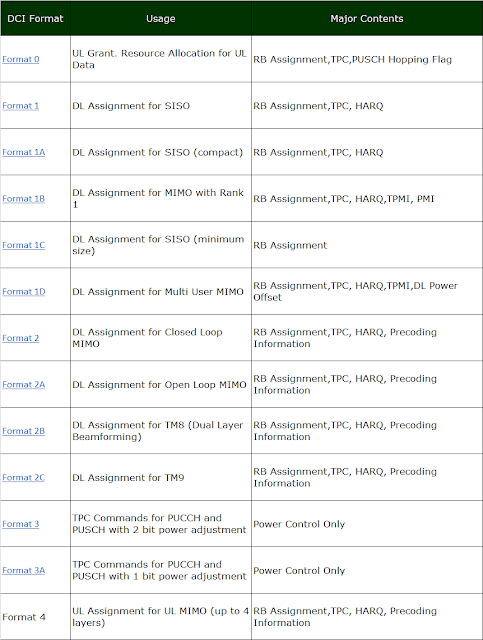
>>DCI
L1 signaling is done by DCI and Up to 8 DCIs can
be configured in the PDCCH. These DCIs can have 6 formats: 1 format for UL
scheduling, 2 formats for Non-MIMO DL scheduling, 1 format for MIMO DL
Scheduling and 2 formats for UL power control.
3GPP TS 36.212 specifies the
range of DCI formats presented in Table 67
- Formats 0 and 4 schedule uplink resources on the
PUSCH
- Formats 1, 1A, lB, 1C, lD, 2, 2A, 2B and 2C
schedule downlink resources on the PDSCH
- Formats 3 and 3A signal TPC commands for the
PUSCH and PUCCH

DCI Format 2A :-------------------------------------------------------------------------------------
This is based on 3GPP 36.212 - 5.3.3.1.5A Format 2A.
Format 2A (Release 13) - C-RNTI, SPS C-RNTI |
Field Name | Length (Bits) | Comment |
Resource allocation header | 1 | RA Type 0 or RA Type 1 |
Resource block assignment for RA Type 0 | 6 (1.4 Mhz) 8 (3 Mhz) 13 (5 Mhz) 17 (10 Mhz) 19 (15 Mhz) 25 (20 Mhz) | Applicable only when Resource allocation header = 0 (RA Type 0) Refer to RA Type page |
| Subset | N/A (1.4 Mhz) 1 (3 Mhz) 1 (5 Mhz) 2 (10 Mhz) 2 (15 Mhz) 2 (20 Mhz) | Applicable only when Resource allocation header = 1 (RA Type 1) Refer to RA Type page |
| Shift | N/A (1.4 Mhz) 1 (3 Mhz) 1 (5 Mhz) 1 (10 Mhz) 1 (15 Mhz) 1 (20 Mhz) | Applicable only when Resource allocation header = 1 (RA Type 1) Refer to RA Type page |
Resource block assignment for RA Type 1 | N/A (1.4 Mhz) 6 (3 Mhz) 13 (5 Mhz) 14 (10 Mhz) 16 (15 Mhz) 22 (20 Mhz) | Applicable only when Resource allocation header = 1 (RA Type 1) Refer to RA Type page |
TPC for PUCCH | 2 | See Power Control section |
Downlink Assignment Index | X | Set only in TDD See 36.212 - Table 5.3.3.1.2-2 See DAI page for the details of DAI concept |
HARQ Process | 3 (FDD) 4 (TDD) | |
Transport block to codeword swap flag | 1 | |
MCS for Transport Block 1 | 5 | |
NDI for Transport Block 1 | 1 | |
RV for Transport Block 1 | 2 | |
MCS for Transport Block 2 | 5 | |
NDI for Transport Block 2 | 1 | |
RV for Transport Block 2 | 2 | |
Precoding information | 0 (2 Antenna) 2 (4 Antenna) | Refer to 36.212 Table 5.3.3.1.5A-2 for the meaning of value in the field |
HARQ-ACK resource offset | 2 | Set only when DCI is carried by EPDCCH |
< 36.212 Table 5.3.3.1.5A-2: Content of precoding information field for 4 antenna ports >
>>PUCCH Format:
·
NOTE : 'Number of Bits' here the bit length after PUCCH channel
coding. In short, the number of ACK/NACK bits does not change by channel coding
process, but the number of CSI (e.g, CQI) increases to 20 bits. See PUCCH Channel Coding page.
- PUCCH formats 1, 1a and 1 b transfer HARQ acknowledgments
and scheduling requests.
- PUCCH formats 2, 2a and 2b transfer HARQ acknowledgements
and CSI reports.
- PUCCH format 3 transfers HARQ acknowledgments
for carrier aggregation and scheduling request.
>> SR request??
is a single bit flag used to request PUSCH resources
from the eNodeB. Scheduling Requests are always transferred using the PUCCH. UE
are provided with configuration information regarding Scheduling Requests
within an RRC Connection Setup, RRC Connection Reconfiguration or RRC
Connection Re-establishment message. The Scheduling Request Configuration Index
can be signaled with a value between 0 and 157. After transmitting the first SR
on PUCCH, if the UE doesn’t receive uplink resources from the eNodeB, then
based on the periodicity, the UE re-sends SR on PUCCH. This process continues
till UE transmits SR for dsr-TransMaxnumber of times on PUCCH if the UE
doesn’t receive uplink resources from the eNodeB. After transmitting SR for
maximum (dsr-TransMax) number of times, the UE releases SR resources (frequency
as well as time), initiates random access procedure and cancels all pending
(triggered) SRs.
- Scheduling request is a single bit flag which is
used to request PUSCH resources from eNodeB.
- In LTE, SR is transmitted using PUCCH channel.
>> What is difference between SR and BSR.
Answer:
If a BSR has been triggered and the UE has UL grant for
transmission in the current TTl, then report a BSR. Otherwise, if the BSR has
been triggered in the current TTl but there are no UL-SCH resources,
then trigger an SR process.
The SR is used for requesting UL-SCH resources, when an SR
is triggered, it would be in pending state until generate a BSR control element
or the UL grant can accommodate all the data for transmission.
The SR is sent on physical uplink control channel (PUCCH) in
normal, if the SR cannot be sent on PUCCH or there is no valid PUCCH resources
then initiate a random access procedure.
UE always keep track of SR transmission on PUCCH. After
reaching the maximum number of SR transmission (SR Max) and UE has not been
allocated any radio resource for uplink transmission, it releases PUCCH
resource for SR and start Random access procedure. This behavior could be
because of bad transmission power, wrong configuration of SR, uplink coverage
is very poor or UE may be in Handover situation. Radio resource for uplink
transmission is granted only after 4ms of SR transmission.
>>
Difference between default bearer and dedicated bearer??
Bearer is just a virtual concept. It defines how the UE data is treated when it travels across the network. Network might treat some data in a special way and treat others normally. Some flow of data might be provided guaranteed bit rate while other may face low transfer.
Example:
Person A will always get at least 256 Kbps download speed on his LTE phone while for person B there is no guaranteed bit rate and might face extremely bad download speed at times
From the LTE specs, the maximum number of bearers that a UE can establish is 11
Let me give a couple of questions to help you understand the behaviour of these two bearers.
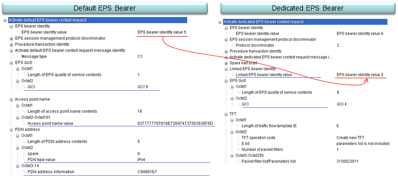
What are the information that Default EPS has but Dedicated EPS bearer does not ?
The answer is "APN Name" and "PDN type/PDN Address".
Then What kind of PDN address does Dedicated EPS Bearer will use ?
The answer is "Dedicated EPS Bearer uses the PDN address of Default EPS Bearer it is linked to".
Then how a Dedicated EPS Bearer knows which Default EPS Bearer it is linked to ?
The answer is that it is via a information element called "Linked EPS Bearer Identity" (See the arrow shown in the picture above)
What are the information that both Default EPS Bearer and Dedicated EPS Bearer has ?
The answer is "QCI".
Can Default EPS Bearer and Dedicated EPS Bearer can have the same QCI value ?
The answer is "No, they must have different QCI value".
What is the relation between Default EPS Bearer and an APN ?
The answer is "there is one-to-one relationship between them. One Default EPS Bearer is allocated for one APN.
LTE layer 2 connectivity with eUTRAN+EPC
- Layer 3 IP (IPv4 or IPv6)connectivity to PDN1, UE IP = IP1
- Default bearer. QoS, EBI = EBI1
- Dedicated bearer 1 with QoS1, EBI = EBI2, LBI = EBI1
- Dedicated bearer 2 with QoS2, EBI = EBI3, LBI = EBI1
- Layer 3 IP (IPv4 or IPv6)connectivity to PDN2, UE IP = IP2
- Only single default bearer. QoS, EBI = EBI4
- Layer 3 IP (IPv4)connectivity to PDN3, UE IP = IP3
- Default bearer. QoS, EBI = EBI5
- Dedicated bearer 1 with QoS3, EBI = EBI6, LBI = EBI5
- Layer 3 IP (IPv6)connectivity to PDN3, UE IP = IP4
- Default bearer. QoS EBI = EBI7
- Dedicated bearer 1 with QoS4, EBI = EBI8, LBI = EBI7
|
|
GBR Vs NON GBR
GBR is a confusing concept at the start when looking at LTE but it’s actually kind of simple when we break it down.
GBR stands for Guaranteed Bit Rate, meaning the UE is guaranteed a set bit rate for the bearer.
The default bearer is always a non-GBR bearer, with best effort data rates.
Let’s look at non-GBR bearers to understand the need for GBR bearers:
As the Uu (Air) interface is shared between many UEs, each is able to transfer data. Let’s take an example of a cell with two UEs in it and not much bandwidth available.
If UE1 and UE2 are both sending the same amount of data it’ll be evenly split between the two.
But if UE1 starts sending a huge amount of data (high bit rate) this will impact on the other UEs in the cells ability to send data over the air as it’s a shared resource.
So if UE2 needs to send a stream of small but important data over the air interface, while UE2 is sending huge amounts of data, we’d have a problem.
To address this we introduce the concept of a Guaranteed Bit Rate. We tell the eNB that the bearer carrying UE2’s small but important data needs a Guaranteed Bit Rate and it reserves blocks on the air interface for UE2’s data.
So now we’ve seen the need for GBR there’s the counter point – the cost.
While UE1 can still continue sending but the eNB will schedule fewer resource blocks to it as it’s reserved some for UE2’s data flow.
If we introduced more and more UEs each requiring GBR bearers, eventually our non-GBR traffic would simply not get through, so GBR bearers have to be used sparingly.
Note: IP data isn’t like frame relay or circuit switched data that’s consistent, bit rate can spike and drop away all the time. GBR guarantees a minimum bit rate, which is generally tuned to the requirements of the data flow. For example a GBR for a Voice over IP call would reserve enough for the media (RTP stream) but no more, so as not to use up resources it doesn’t need.
QCI = 1
: Resource Type = GBR, Priority = 2, Packet Delay Budget = 100ms, Packet Error Loss Rate = 10-2 , Example Service = Voice
QCI = 9
: Resource Type = Non-GBR, Priority = 9, Packet Delay Budget = 300ms, Packet Error Loss Rate = 10-6, Example Service = Internet
The specific QCI value is allocated for each UE and is informed to UE via 'Activate default EPS bearer context request' message as shown below. (Followings are just a couple of examples.)
Activate default EPS bearer context request ::= DIVISION
. ...
EPS quality of service
Length: 1
Quality of Service Class Identifier (QCI): QCI 9 (9)
Activate dedicated EPS bearer context request ::= DIVISION
. ...
EPS quality of service
Length: 5
Quality of Service Class Identifier (QCI): QCI 1 (1)
Maximum bit rate for uplink : 1 kbps
Maximum bit rate for downlink : 1 kbps
Guaranteed bit rate for uplink : 1 kbps
Guaranteed bit rate for downlink : 1 kbps
SRB Vs DRB
Answer:
SRB: These Radio Bearers (RB) are used only for the
transmission of RRC and NAS messages
DRB: These are used to carry user plane traffic.
SRB =>
- SRB0 is for RRC messages using the CCCH logical channel
- SRB1 is for RRC messages (which may include a piggybacked
NAS message) as well as for NAS messages prior to the establishment of SRB2,
all using DCCH logical channel
- SRB2 is for RRC messages which include logged
measurement information as well as for NAS messages, all using DCCH logical
channel. SRB2 has a lower-priority than SRB1 and is always configured by
E-UTRAN after security activation
DRB=> is established for the transmission of data plane
packets. Multiple DRBs can be established for an UE due to different types of
services used by UE such as internet browsing, voip call etc. A UE can have
maximum of eight data radio bearers at a particular moment.
If EPS
bearer ID is = x +4 ; //EPS bearer id=5
Then
DRB ID
= x; #x=1
Logical
Channel ID = x + 2; //Loch id =3
NOTE : All these ranges is with respect to DRB establishment
EPS Bearer ID Range is INTEGER (0..15) (But 0-4 is reserved
so we use starting from 5 )
DRB ID Range is INTEGER (1..32) (As in LTE max 8 DRB can be established per UE
so we use from 1-8)
Logical Channel ID range for DRBs is INTEGER (3..10) ( For for DRB1 we use 3 as
logical channed ID)
36.331 section 6.4. states the maximum amount of DRB
(Data Radio Bearers) is 11.
However, if you look at Annex B.1 (Feature
Group Indicators) and the description of index 20, the minimum requirement for
a Rel-8 UE is to support SRB1, SRB2 and 4 RLC AM DRB's, and an extra RLC UM DRB
if RLC UM is supported. If index 20 indicates "1", the UE shall
support (in addition to SRB1 and SRB2) up to 8 RLC AM DRB's, or 5 RLC AM DRB's
plus up to 3 RLC UM DRB's, and any subset of these.
>> What is DRX: is a mechanism in which UE gets into sleep mode for a
certain period of time and wake up for another period of time.


No comments:
Post a Comment
If You have any concern you are free to message/comment me.