Multiplexing and Demultiplexing in Transport Layer
Prerequisite – Layers of OSI Model
Multiplexing and Demultiplexing services are provided in almost every protocol architecture ever designed. UDP and TCP perform the demultiplexing and multiplexing jobs by including two special fields in the segment headers: the source port number field and the destination port number field.
Multiplexing –
Gathering data from multiple application processes of sender, enveloping that data with header and sending them as a whole to the intended receiver is called as multiplexing.
Demultiplexing –
Delivering received segments at receiver side to the correct app layer processes is called as demultiplexing.

Figure – Abstract view of multiplexing and demultiplexing

There are two types of multiplexing and Demultiplexing :
- Connectionless Multiplexing and Demultiplexing
- Connection-Oriented Multiplexing and Demultiplexing
How Multiplexing and Demultiplexing is done –
For sending data from an application at sender side to an application at the destination side, sender must know the IP address of destination and port number of the application (at the destination side) to which he want to transfer the data. Block diagram is shown below :
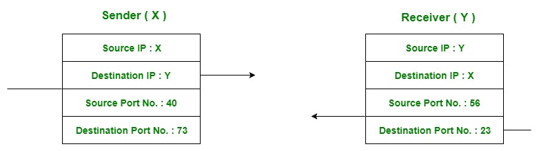
Figure – Transfer of packet between applications of sender and receiver
Let us consider two messaging apps that are widely used now a days viz. Hike and whatsapp. Suppose A is the sender and B is the receiver. Both sender and receiver have these applications installed in their system (say smartphone). Suppose A want to send messages to B in whatsapp and hike both. In order to do so, A must mention the IP address of B and destination port number of the whatsapp while sending the message through whatsapp application. Similarly, for the later case, A must mention the IP address of B and destination port number of the hike while sending the message.
Now the messages from both the apps will be wrapped up along with appropriate headers(viz. source IP address, destination IP address, source port no, destination port number) and sent as a single message to the receiver. This process is called multiplexing. At the destination, received message is unwrapped and constituent messages (viz messages from hike and whatsapp application) are sent to appropriate application by looking to the destination the port number. This process is called demultiplexing. Similarly, B can also transfer the messages to A.

Figure – Message transfer using whatsapp and hike messaging application
TCP and UDP Headers
The UDP header (8 bytes) is considerably much smaller than the TCP header (20 bytes). Both the UDP and TCP header contain 16 bit source and destination Port fields.
The source port field is used to reply to the message.
There is a good diagram of both headers here.
TCP and UDP ports
Both TCP and UDP protocols use ports. You can have an application running on a computer using TCP port 80 and another application using UDP port 80.
An application address is effectively:
IP address + protocol (TCP or UDP) + port number.
The diagram below is meant to illustrate this:


Internet Protocol (IP)
As seen in the figure above, the Internet protocol stack provides a connection oriented reliable branch (TCP) and an connectionless unreliable branch (UDP) both build on top of the Internet Protocol.The Internet Protocol layer in the TCP/IP protocol stack is the first layer that introduces the virtual network abstraction that is the basic principle of the Internet model. All physical implementation details (ideally even though this is not quite true) are hidden below the IP layer. The IP layer provides an unreliable, connectionless delivery system. The reason why it is unreliable stem from the fact the protocol does not provide any functionality for error recovering for datagrams that are either duplicated, lost or arrive to the remote host in another order than they are send. If no such errors occur in the physical layer, the IP protocol guarantees that the transmission is terminated successfully.
The basic unit of data exchange in the IP layer is the Internet Datagram. The format of an IP datagram and a short description of the most important fields are included below:
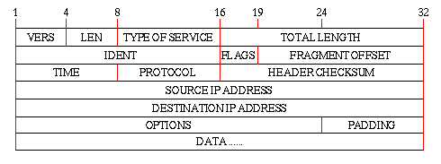
- LEN
- The number of 32 bit-segments in the IP header. Without any OPTIONS, this value is 5
- TYPE OF SERVICE
- Each IP datagram can be given a precedence value ranging from 0-7 showing the importance of the datagram. This is to allow out-of-band data to be routed faster than normal data. This is very important as Internet Control Message Protocol (ICMP) messages travels as the data part of an IP datagram. Even though an ICMP message is encapsulated in a IP datagram, the ICMP protocol is normally thought of as a integral part of the IP layer and not the UDP or TCP layer. Furthermore, the TYPE OF SERVICE field allows a classification of the datagram in order to specify is the service desired requires short delay time, high reliability or high throughput. However, in order for this to have any effect, the gateways must know more than one route to the remote host and as described in the Introduction, this is not the case.
- IDENT, FLAGS, and FRAGMENT OFFSET
- These fields are used to describe fragmentation of a datagram. The actual length of an IP datagram is in principle independent of the length of the physical frames being transferred on the network, referred to as the network's Maximum Transfer Unit (MTU). If a datagram is longer than the MTU then it is divided in to a set of fragments having almost the same header as the original datagram but only the amount of data that fits into a physical frame. The IDENT flag is used to identify segments belonging to the same datagram, and the FRAGMENT OFFSET is the relative position of the fragment within the original datagram. Once a datagram is fragmented it stays like that until it receives the final destination. If one or more segments are lost or erroneous the whole datagram is discarded.
However, the underlying network technology is not completely hidden below the IP layer in spite of the fragmentation functionality. The reason is that the MTU can vary from 128 or less to several thousands of bytes dependent of the physical network (Ethernet has a MTU of 1500 bytes). It is hence question of efficiency when choosing the right datagram size so that fragmentation is minimized. It is recommended that gateways are capable of handling datagrams of at least 576 bytes without having to use fragmentation.
- TIME
- This is the remaining Time To Live (TTL) for a datagram when it travels on the Internet. The Routing Information Protocol (RIP) specifies that at most 15 hops are allowed.
- SOURCE IP-ADDRESS and DESTINATION IP-ADDRESS
- Both the source and destination address is indicated in the datagram header so that the recipient can send an answer back to the transmitting host. However, note that only the host address is specified - not the port number. This is because the IP protocol is an IMP-to-IMP protocol - it is not an end-to-end protocol. A layer more is needed to actually specify which two processes on the transmitting host and the final destination that should receive the datagrams.
User Datagram Protocol (UDP)
The User Datagram Protocol (UDP) is a very thin protocol build on top of the Internet Protocol. The basic unit of data is a User datagram and the UDP protocol provides the same unreliable, connectionless service transferring user datagrams as the IP protocol does transferring its datagrams. The main difference is that the UDP protocol is an end-to-end protocol. That is, it contains enough information to transfer a user datagram from one process on the transmitting host to another process on the receiving host. The format of a user datagram is illustrated below: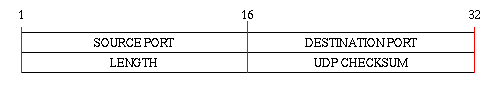
The LENGTH field is the length of the user datagram including the header, that is the minimum value of LENGTH is 8 bytes. The SOURCE PORT and DESTINATION PORT are the connection between a IP-address and a process running on a host. A network port is normally identified by an integer. However, the user datagram does not contain any IP-address so how does the UDP protocol know when the final destination is reached?
When calculating the CHECKSUM header, the UDP protocol appends a 12-byte pseudo header consisting of the SOURCE IP-ADDRESS, the DESTINATION IP-ADDRESS and some additional fields. When a host receives a UDP datagram it takes the UDP header and creates a new pseudo header using its own IP-address as the DESTINATION IP-ADDRESS and the SOURCE IP-ADDRESS extracted from the IP datagram. Then it calculates a checksum and if it equals the UDP checksum, then the datagram has received the final destination.
As indicated in the Internet Protocol Stack Figure the UDP protocol is often used as the basic protocol in client-server application protocols such as TFTP, DNS etc. where the overhead of making a reliable, connection oriented transmission is considerable. This problem will be considered further in the next two sections.
Transmission Control Protocol (TCP)
The Transmission Control Protocol provides a full duplex, reliable, connection oriented service to the application layer as indicated in the Internet Protocol Stack Figure. This section described the basic principle of the TCP protocol and how it provides a reliable service to the application layer protocols.The TCP protocol is a stream oriented protocol. It is designed to provide the application layer software with a service to transfer large amount of data in a reliable way. It establishes a full duplex virtual circuit between the two transmitting hosts so that both host simultaneously can put data out on the Internet without specifying the destination host once the connection is established. In the Transactional Transmission Control Protocol (T/TCP) section an client-server based extension to the TCP protocol is presented as an alternative to the stream architecture.
TCP Segment Format
A segment is the basic data unit in the TCP protocol. As much of the following sections are based on this data unit, the format is presented here: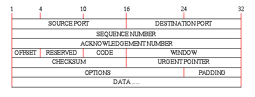
- SOURCE PORT, DESTINATION PORT
- The TCP protocol uses the same trick of using a pseudo header instead of transmitting the source IP-address and the destination IP-address as is already included in the IP-datagram. Therefore only the port numbers are required to uniquely define the communicating hosts.
- CODE
- This field is used to indicate the content of the segment and if a specific action has to be taken such as if the sender has reached EOF in the stream.
- OPTIONS
- The TCP protocol uses the OPTIONS field to exchange information like maximum segment size accepted between the TCP layers on the two hosts. The flags currently defined are
- URG Urgent pointer field is valid
- ACK Acknowledgement field is valid
- PSH This segment requests a push
- RST Reset the connection
- SYN Synchronize sequence numbers
- FIN Sender has reached end of its byte stream
- OFFSET
- This integer indicates the offset of the user data within the segment. This field is only required as the number of bits used in the OPTIONS field can vary
- URGENT POINTER
- This field can be initialized to point to a place in the user data where urgent information such as escape codes etc. are placed. Then the receiving host can process this part immediately when it receives the segment.
Reliable Transmission
At the IP-protocol layer packets can get discarded due to network congestion, noise gateway failure etc. In order to provide a reliable service, the TCP must recover from data that is damaged, lost, duplicated, or delivered out of order by the Internet communication system. This is achieved by assigning a SEQUENCE NUMBER to each byte transmitted, and requiring a positive acknowledgment (ACK) from the receiving host. If the ACK is not received within a timeout interval, the data is retransmitted. At the receiver, the sequence numbers are used to correctly order segments that may be received out of order and to eliminate duplicates. Damage is handled by adding a checksum to each segment transmitted, checking it at the receiver, and discarding damaged segments. The principle is illustrated in the figure below: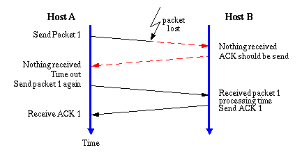
Host A is transmitting a packet of data to Host B, but the packet gets lost before it reaches its destination. However, Host A has set up a timer when to expect the ACK from Host B so when this timer runs out, the packet is retransmitted. The difficult part of the method is to find a value of the time out period as a TCP segment can travel through different speed networks with different loads. This means that the Round trip Time (RTT) can vary from segment to segment. A simple way of calculating the RTT is by using a recursive mean value with an exponential window to decrease the importance of old values.
As mentioned in the introduction to the TCP section, the protocol is a stream oriented protocol. It uses unstructured streams with no method of indexing the user data, e.g. as records etc. Furthermore, the length of a TCP segment can vary as is the case for the IP-datagram and the UDP user datagram. Therefore the acknowledgement can not be based on the segment number but must be based on bytes successfully transferred.
However, the PAR principle is very inefficient as the sending host must await the acknowledgement before it can send the next segment. This means that the the minimum time between two segments is 1 RTT plus the time required to serve the segments at both ends. The TCP protocol solves this by using sliding windows at both ends.
This method permits the transmitting host to send as many bytes as can be stored in the sending window and then wait for acknowledgements as the remote host receives the segments and sends data in the other direction. The acknowledgement send back is cumulative so that it at all times shows the next byte that the receiving host expects to see. An example with a large window size and selective retransmission is shown in the figure:
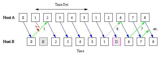
Byte number 1 is lost so Host B never sends back a positive acknowledgement. When Host A times out on byte 1 it retransmit it. However, as the rest of the bytes from 2-5 are transmitted successfully the next acknowledgement can immediately jump to 6 which is the next expected byte. Byte 2 is also retransmitted as Host A does not know exactly how many bytes are erroneous. Host B just discards byte 2 as it already is downloaded.
The window technique can also be used to provide a congestion control mechanism. As indicated in the TCP Segment Format Figure every segment has a WINDOW field that specifies how much data a host is willing to receive. If the host is heavyly loaded, it can decrease the WINDOW parameter and hence the transmission speed drops.
However, as the TCP protocol is an end-to-end protocol it can not see if a congestion problem has occurred in an intermediate Interface Message Processor (IMP) (often called a packet switched node) and hence, it has no means to control it by adjusting the window size. TCP solves this problem by using the Internet Control Message Protocol (ICMP) source quench messages.
No comments:
Post a Comment
If You have any concern you are free to message/comment me.