Digital Modulation
Digital modulation is concerned with mapping of the bits (1s and 0s) to a property of the signal suitable for transmission. For example, consider a rectangular pulse shape. Amplitude modulation maps 0s and 1s to as
that correspondingly alters the amplitude of the rectangular pulse shape, as shown in Figure 2 below.

Figure 2: Amplitude modulation
Here, a bit stream 01001010 is mapped to the sequence -1,+1,-1,-1,+1,-1,+1,-1. In this simple system, all the Rx has to do is compare the amplitude of the received signal level (within each bit time) to a threshold (say, 0) and decide in favor of +1 or -1 (and consequently, 1 or 0).
A Low Data Rate Signal
Suppose that the year is early 2000s and our hiker in Figure 1 only wants to check his email and/or messages (probably driven by what is available) and requires a data rate of only kbps. That translates to a bit time (also known as bit duration) of
as drawn in Figure 3.

Figure 3: A low rate kbps signal with a bit duration equal to
As described above, the first and second multi-path components arrive and after the direct path, respectively (ignoring the carrier). This is shown in Figure 4.

Figure 4: First and second multipath components arriving after and after the direct path, respectively (carrier wave not shown)
Since nature adds the signals at the antenna, the Rx will have a summation of these three paths, effectively the same signal delayed by different amounts but with different attenuation and phase shifts of the carrier waves (not drawn in the figure). Those phase shifts depend on the path delay and the carrier frequency. Observe that is of the bit duration , an implication of which is that multi-path components will distort the Rx signal but there will not be much interference among the bits themselves. That is to say that bit 1 through its last path will interfere slightly with bit 2 to a little extent but not with any other bit farther than that.
This is a situation that can be handled without much effort in terms of computational resources. We claim that the wireless channel does not pose a significant problem to Rx processing time in this low data rate scenario. It is not necessary to understand this in the context of this article but the disadvantage here is that in case of destructive interference, there is no other way to recover except providing diversity to the Tx signal. Diversity is a signal replica in some form whether in time, frequency, space, etc.
Moving towards High Data Rate
Fast forward to a decade, say early 2010s. Escaping the fast pace of life, our hiker wants to sit on top of that peaceful mountain .... to watch YouTube videos. In fact, he considers having access to it anywhere as a basic necessity of life like water and electricity. Assume that a data rate of Mbps is needed for this purpose, which translates to a bit duration of as shown in Figure 5.

Figure 5: A high rate Mbps signal with a bit duration equal to
The main point is that the environment is still the same and does not care about our data rates! Multi-path components previously arriving and after the direct path will still arrive and after the direct path. This is illustrated in Figure 6 (again ignoring the carrier). The different path lengths will translate into different attenuations and phase shifts resulting in constructive and destructive interference throughout the signal span.

Figure 6: First and second multipath components still arrive after and after the direct path, respectively (carrier wave not shown)
What does this imply for the high rate transmission? Notice that in this case, the initial bits of the transmission are interfering with many tens of bits in the future through the late arriving paths, a phenomenon known as Inter-Symbol Interference (ISI). In most cases of interest, this ISI could have been observed even extending to hundreds or even thousands of bits. We can conclude that the same harmless channel for low rate communication has become harsh for high rate communication!
A solution must be devised for this problem.
Solution - Equalizer
It turns out that a solution for this kind of problem was devised by Robert Lucky at Bell Labs in 1964: an adaptive equalizer. An equalizer is a filter that mitigates the effects of channel fading on the Rx signal and removes the Inter-Symbol Interference (ISI). Its input is the distorted waveform (sum of the original signal and its multi-path components) and the output is the clean desired bit stream as shown in Figure 7.
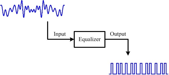
Figure 7: Equalizer input is a distorted waveform and its output is a clean bit stream
Don't think of it as a physical device. Just like everything physical got transformed into digital logic in the history of communications (leading to software defined radios), an equalizer sits as mere lines of code in a microprocessor.
An equalizer has its advantages and disadvantages. Needless to say, it considerably improves the bit error rate and consequently fundamental to making the system functional. Technically, it exploits the frequency diversity available in a broad spectrum. On the other hand, for a high rate system, it is the most demanding and resource intensive component of a conventional wireless Rx. While the exact numbers depend on the requirements and implementation, it can consume even 75% of the processing resources! In high speed communication, it is impractical to be busy processing a bit in a certain window of time while many future bits are arriving at the Rx. That will result in filling the buffer faster than being emptied.
We can conclude that a low data rate communication requires a relatively simple Rx processor while high rate communication requires a heavy duty Rx processor. That kind of processing demands high power consumption and hence not feasible for battery operated devices like our smart phones.
Can there be a technique to achieve fast communication with a simpler equalizer? The answer is yes and the technique is OFDM.
OFDM in Time Domain
In time domain, OFDM breaks one serial fast bit stream into many parallel slow bit streams. Then, these parallel slow bit streams are multiplied with orthogonal sinusoids, where orthogonality between two sinusoids is defined with a summation over a certain time interval as
when .
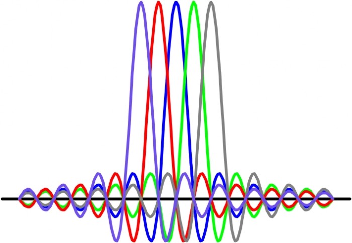
This process is illustrated in detail in Figure 8 with the help of an example:
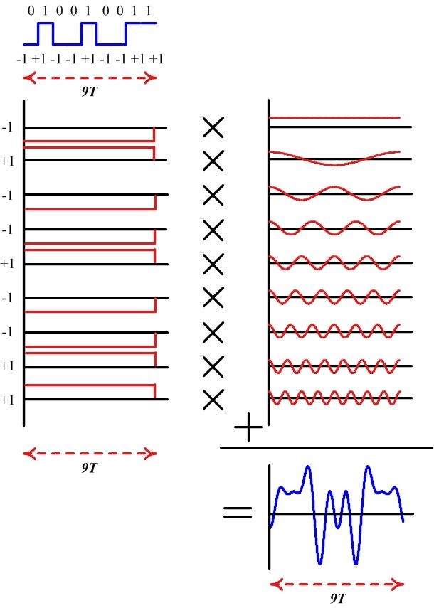
Figure 8: An OFDM example in time domain. See below for details
For a bit stream , the example in Figure 8 traces the following steps:
I. Assume that the bit duration is and there are 9 bits to be sent. In a high speed communication system, it will take seconds to transmit all the bits. So we break them down to 9 parallel bit streams each with a duration of seconds.
II. Assume a fundamental frequency of with 9 samples within this duration (that will be one complete period). Then, this sinusoid will be orthogonal to 8 other sinusoids with frequencies , , , , . This set of 9 sinusoids is shown in Figure 8. We will call them subcarriers.
III. Next, we multiply each such sinusoid with or (depending on the bit) to scale their amplitude accordingly.
IV. Finally, all these amplitude scaled sinusoids are added together to generate the desired signal. Notice that this composite signal has a duration of seconds (same duration as the original bit stream) but contains the information from all 9 bits.
For a bit stream mapped to a non-binary modulation scheme (having I and Q components) and sinusoids (instead of 9), this sequence of steps can be carried out using the inverse Discrete Fourier Transform (iDFT) defined as
The question is what we have achieved so far. For each such individual signal, the multi-path components arrive in not too distant future (just like a low rate stream above). The multi-path components for individually modulated subcarriers as well as for the composite signal are shown in Figure 9.
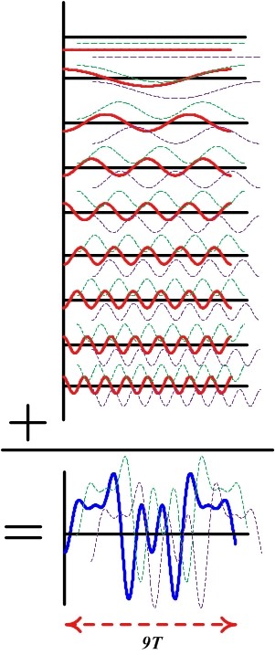
Hence, the equalizer design is easy having less spread paths and consequently less interference with future symbols, provided that we find a way to separate the subcarriers at the Rx. Separating these bits at the Rx is easy: we can correlate (multiply sample by sample and sum) the composite signal with just one subcarrier, say with frequency . Utilizing their orthogonality property, contribution from all other 8 subcarriers will cancel out to zero, while the contribution from the subcarrier with that frequency will pop out, scaled in amplitude by our modulation signal. The same procedure can be repeated for all other subcarriers.
Essentially, this is an operation of Discrete Fourier Transform (DFT) as
which, for each , will generate our modulate data.
OFDM in Frequency Domain
The wireless channel shown in Figure 1 has an impulse response derived from the contribution of each multi-path component. It also has a frequency response, assume that it has a shape as in Figure 10.

Figure 10: Frequency response of the wireless channel
With respect to frequency domain, the signal at the Rx is a product of the spectra of the Tx signal and the wireless channel. Thus, the channel will allow some frequencies to pass through unharmed while suppressing some others. We will come to this point later.
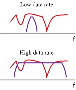
Now remember that time and frequency have inverse relationship. A signal wide in time domain has a narrow frequency span and vice versa. Although this relationship can be derived, we can just look into the Fourier transform of a rectangular signal: a sinc signal. The wider the rectangle, the earlier the sinc's first zero-crossing is. Therefore, a low rate signal being wide in time domain has a narrow spectral representation. On the other hand, a fast rate signal exhibiting rapid changes in time has a wide spectrum. While random data generates a random signal that in turn is defined in terms of power spectral density, the underlying concept is still true and is drawn in Figure 11.
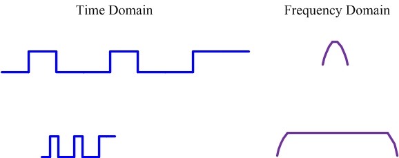
Figure 11: Spectral contents of a signal depend on its variations in time
There can be a question of how to recover when the narrowband signal appears within a deep channel fade. In that case, nothing but diversity (a signal replica in some form whether in time, frequency, space, etc.) can recover the signal which is out of scope of this article.
On the other hand, a high data rate signal needs a lot of Rx processing to equalize the channel. Figure 12 illustrates how different portions of the signal spectrum are treated differently by the channel and a complex algorithm needs to be implemented for signal recovery. There is an advantage in this situation in the form of available 'frequency diversity' which prevents the whole signal spectrum to go down in a deep fade (as opposed to low data rate case above). Equalizer inherently exploits that same frequency diversity which is outside the scope of this article. However, remember that we cannot afford a computationally expensive equalizer and instead need a simpler one.
To solve this problem, what OFDM does in frequency domain is fairly simple. It just segments the available bandwidth into many parallel almost flat channels through utilizing those sinusoidal subcarriers. Hence, equalization for each narrow slice requires just a single division operation, rendering the computational load of the equalizer to a total of divisions. This is illustrated in Figure 13.

Figure 13: In frequency domain, OFDM slices the spectrum through using the subcarriers; now each spectral segment can be processed individually
The situation is very similar to processing a bread. Each time a person wanted to eat bread, they had to take a knife and cut a piece of bread for themselves. Then came sliced bread in 1928 that changed everything. Processing each individual slice got much easier; you could put jam, butter or cheese on different slices. See Figure 14 below.

It was difficult to process a whole bread before that invention. Similarly, it is difficult to process the collective spectrum for communication purposes. By slicing the spectrum, OFDM not only made it easier to equalize the wireless channel but also made it possible to send different modulation signals on different subcarriers (e.g., subcarriers experiencing 'good' channel can be used to transmit a higher-order modulation signal that translates into more bits within the same time). On a lighter note, now we have a formal proof that OFDM is the best thing since sliced bread.
Summary
- In time domain, OFDM converts one serial fast bit stream into many parallel slow bit streams.
- In frequency domain, OFDM segments one wide spectrum into many narrow spectra.
Remarks
There are two remarks for readers who might have the following questions in their minds, which can be skipped by everyone else.
1. A question that can be asked at this stage is that why OFDM figure in articles and textbooks looks different than Figure 13. The reason is that a sinusoidal subcarrier has a spectral shape that is a single impulse. However, when that sinusoid is limited in time, it is equivalent to multiplying it with a rectangular signal. Since Fourier transform of a rectangle is a sinc signal, and multiplication in time domain is convolution in frequency domain, we get a sinc signal for each subcarrier - shifted in frequency according to the frequency of that subcarrier. The actual OFDM spectrum, though still sliced, is drawn in Figure below.
2. How does OFDM eliminate the ISI arising from the neighboring symbols (like the multi-path in above figures)? For this purpose, a gap can be left between two subsequent symbols so that multi-path components of the first do not interfere with the second. However, for numerous reasons, something known as a cyclic prefix is actually used.
No comments:
Post a Comment
If You have any concern you are free to message/comment me.