SRS (Sounding Reference Signal)
The Sounding Reference Signal (SRS) is a reference signal transmitted by the UE in the uplink direction which is used by the eNodeB to estimate the uplink channel quality over a wider bandwidth. The eNodeB may use this information for uplink frequency selective scheduling.
The eNodeB can also use SRS for uplink timing estimation as part of timing alignment procedure, particularly in situations like there are no PUSCH/PUCCH transmissions occurring in the uplink for a long time in which case, the eNodeB relies on SRS for uplink timing estimation.
There are 3 types of SRS transmissions defined in LTE. From release-8 onwards ‘Single SRS’ transmission and ‘Periodic SRS’ transmissions are supported. In release-10, ‘Aperiodic SRS’ transmission is introduced. We will be discussing each of these types in detail.
UE specific SRS configuration for ‘trigger type 0’ (Periodic or Single)

UE specific SRS configuration for ‘trigger type 1’ (Aperiodic)

In addition to the UE specific SRS configuration, cell specific SRS configuration defines the subframes that can contain SRS transmissions as well as the set of SRS bandwidths available in the cell. In order to prevent SRS transmissions in the PUCCH regions of the cell, several SRS bandwidth configurations (srs-SubframeConfig) are defined.

Single and Periodic SRS transmissions
Single SRS transmission is very simple one. After receiving RRC Connection Reconfiguration message with UE specific SRS configuration and parameter duration set to FALSE, the UE transmits SRS only once which is called ‘Single’ SRS transmission.
If the parameter duration is set to be TRUE, then the UE transmits Periodic SRS indefinitely until disabled.
srs-ConfigIndex defines SRS periodicity and an offset. The periodicity ranges from 2 ms to 320 ms.
srs-HoppingBandwidth is defined for the purpose of frequency hopping of SRS. If frequency hopping of the SRS is enabled, then srs-HoppingBandwidth is smaller than srs-Bandwidth. SRS hopping procedure will also be discussed in detail.
freqDomainPosition defines the starting position of the SRS in the frequency domain
transmissionComb: Actually, SRS is transmitted in every alternate (every even or every odd) subcarrier in the assigned SRS bandwidth. transmissionComb takes values 0 or 1 which informs whether to transmit SRS in every even or odd subcarrier in the assigned SRS bandwidth. By doing this the eNodeB can multiplex two UEs with same cyclicShift, frequency and time resources but different transmissionComb (0 or 1).
It depends on the configuration set by the signaling message (SIB2, RRC Connection Setup, RRC Connection Reconfiguration etc), but UE can transmit it every two subframes at the most and every 32 frame (320 subframe) at the least (10 bit signaling parameter srs-ConfigIndex tells UE of
the periodicity of SRS transmission and the period can be 2,5,10,20,40,80,160,320 ms). Actually
there is an option in which UE does not transmit SRS at all.
SRS is transmitted at the last symbol of UL slot with full system band area and it is transmitted by a certain interval. What if multiple UE has the same SRS transmission cycle(interval) ? Would there be any possibility that a bunch of SRS from multiple UEs are overlapped ?
Yes, this is possible. To avoid this kind of situation, we can configure each of UE to transmit SRS in hopping mode with different hopping schedule.
As I mentioned earlier, SRS configuration is notified to UE by a couple of RRC messages. Common RRC messages carrying SRS configuration info are SIB2, RRC Connection Setup, RRC Connection Reconfiguration.
There are largely two kinds of SRS, Common SRS and Dedicated SRS. Common SRS is also called Cell Specific SRS and Dedicated SRS is also called UE Specific SRS.
In SIB2, SRS is configured in following information elements. You can disable SRS by setting soundingRS-UL-ConfigCommon if you want.
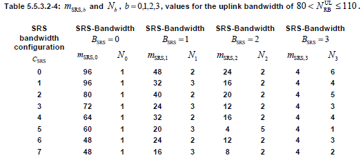
For srs-Bandwidth, refer to following tables from 36.211. Basically these tables defines how many resource block (frequency bandwidth) is allocated for SRS transmission.
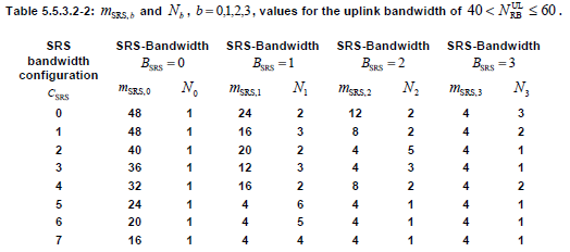
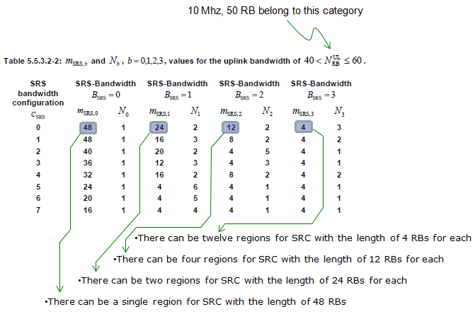
 An example of how to interpret the above table is as follows
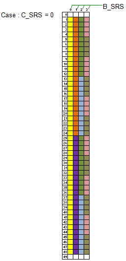
If I convert the above description, it can be illustrated as shown below.
 \
\
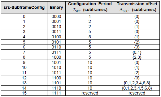
For srs-SubframeConfig, please refer to the following table from 36.211. Since srs-SubframeConfig is parameter only for SRS Common (Cell Specific SRS), this table is applied only for Cell Specific SRS. Basically this table defines on which subframe SRS is transmitted and on which subframe it is not transmitted.
< 36.211 - Table 5.5.3.3-1: Frame structure type 1 sounding reference signal subframe configuration >
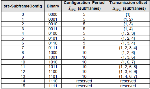
< 36.211 - Table 5.5.3.3-2: Frame structure type 2 sounding reference signal subframe configuration >
How do we know from the table above, which subframe should transmit SRS or which subframe should not ? It is determined by the following rule.
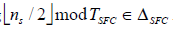
Where ns here means "slot number within a radio frame".
For example, if we chose subframe configuration 7(Frame structure type 1), T_SFC become 5 and Delta_SFC become {0,1}. According to this, the SRS Status on each subframe become as follows.
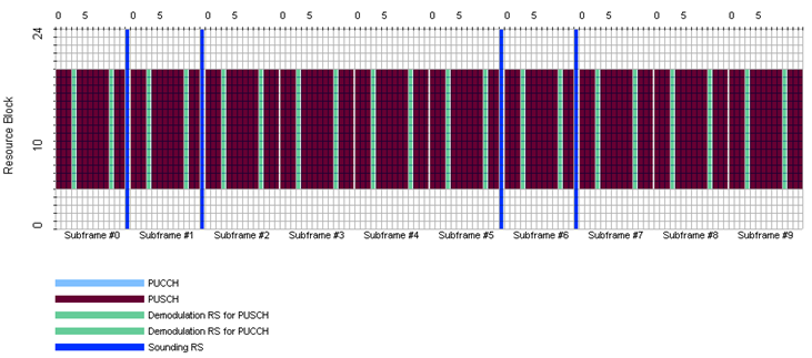
Following is an example frame structure showing the SRS transmission determined by the above table. (In this example, System BW = 5 Mhz, Start RB = 5, Number of RB = 15)
< Uplink Frame Structure with SRS >
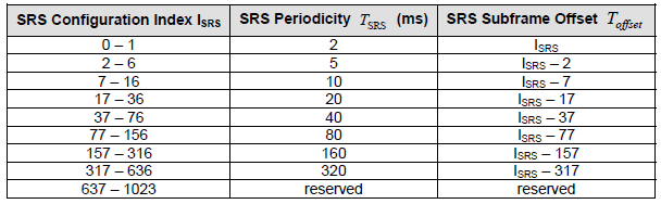
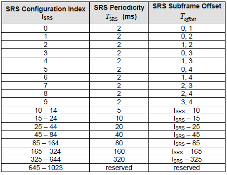
For srs-ConfigIndex, please refer to the following table from 36.213.
< 36.213 - Table 8.2-1: UE Specific SRS Periodicity T_SRS and Subframe Offset Configuration T_offset for trigger type 0, FDD >
For the following parameters, refer to 36.211 5.5.3.2 Mapping to physical resources.
One thing to notice that there is no flag for "srs-Hopping ON or OFF", but according to the specification (if I understood it correctly) we can figure "srs-Hopping ON or OFF" indirectly by combining the following two parameters.
srs-HoppingBandwidth >= srs-Bandwidth : SRS Hopping OFF
srs-HoppingBandwidth < srs-Bandwidth : SRS Hopping ON
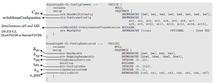
If you read through the 36.211, you would notice that many of these parameters are coming from higher layer. Following is the higher layer message and I associated each of the information elements to the parameters you saw in previous process.
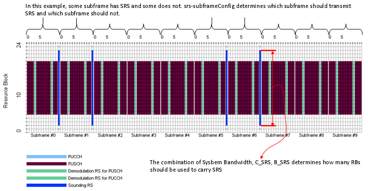
Unfortunately most of parameters related in SRS creation/resource allocation is hard to visualize, but there are at least a couple of parameters that can be visualized as follows.
< Uplink Frame Structure with SRS - Example on srs-subframeConfig >
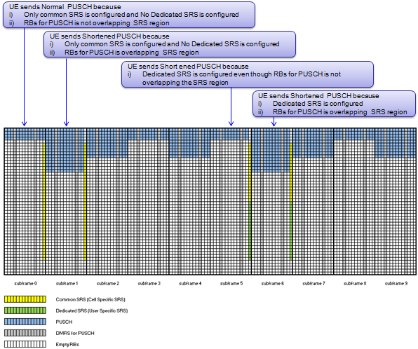
Once Common SRS and Dedicated SRS are configured, UE has to determine whether it transmit Normal PUSCH or Shortened PUSCH everytime it try to send PUSCH. Following example would help you understand the decision making criteria.
Since the system Bandwidth is 50 PRBs, there are a total of 600 subcarriers (0…599)
Example 1: Wide band SRS (no SRS Hopping)
Consider srs-Bandwidth = bw0 and srs-HoppingBandwidth = hbw0.
Since srs-Bandwidth is equal to srs-HoppingBandwidth, frequency hopping is not enabled.
In the subframe where SRS is transmitted, starting from subcarrier number 13, every alternate subcarrier (13, 15, 17… 585, 587) is used for SRS transmission.
The eNodeB can allocate same time and RBs for another UE by setting transmissionComb = 0 (all other parameters are same).
Example 2: SRS Frequency Hopping
If frequency hopping of the SRS is enabled, then srs-HoppingBandwidth is smaller than srs-Bandwidth.
Consider two UEs, UE1 and UE2. Let transmissionComb = 0 for both of the UEs and freqDomainPosition = 0 for UE1 and freqDomainPosition = 2 for UE2.
Since srs-Bandwidth is set to 3, both of the UEs use 4 RBs in every subframe for SRS transmission.

There can be a lot of combinations considered. In a single subframe, the eNodeB can configure all 48 PRBs to UE1 with transmissionComb = 0, and configure a couple of UEs with 4 PRBs but using transmissionComb = 1. Similarly, other combinations of various SRS bandwidths of 4, 12, 24, and 48 resource blocks can be considered
Time domain resource selection for SRS transmission
In the time domain, a resource is nothing but the subframe where SRS transmission has to happen.
Based on srs-SubframeConfig in SIB2, the UE first derives cell specific SRS subframe. These subframe (s) are common to all the UEs in the cell.
Different UEs are configured with different UE specific SRS configuration, based on which each UE derives UE specific SRS subframe.
The UE transmits SRS only if the ‘UE specific SRS subframe’ coincides with ‘Cell specific SRS subframe’.
Example: Let us consider srs-SubframeConfig = sc8 and srs-ConfigIndex = 0.
From Table 5.5.3.3-1 in 36.211, subframes 2, 3, 7, and 8 are cell-specific subframes. From srs-ConfigIndex, UE specific subframes are 0, 2, 4, 6, and 8. So the UE transmits SRS in subframes 2 and 8.
When SRS is being transmitted by a UE in a subframe, it may overlap in frequency with PUSCH being transmitted by another UE. Due to this reason, none of the UEs in the cell transmits PUSCH in the last OFDM symbol of a cell specific SRS subframe. Since all UEs are aware of cell specific SRS configuration, they can take care of not transmitting PUSCH in the last OFDM symbol of the cell specific SRS subframe.
A UE does not transmit SRS whenever SRS and CQI transmissions happen to coincide in the same subframe.
A UE shall not transmit SRS whenever SRS transmission and PUCCH transmission carrying HARQ-ACK and/or Scheduling Request happen to coincide in the same subframe if the parameter ackNackSRS-SimultaneousTransmission in SIB2 is set to FALSE.
A UE shall transmit SRS whenever SRS transmission and PUCCH transmission carrying HARQ-ACK and/or Scheduling Request using shortened PUCCH format happens to coincide in the same subframe if the parameter ackNackSRS-SimultaneousTransmission is TRUE. In this case, the UE shall transmit shortened PUCCH format where the HARQ-ACK or the SR symbol corresponding to the SRS location is punctured.
The UE shall use shortened PUCCH format in a cell specific SRS subframe even if the UE does not transmit SRS in that subframe.
In case both periodic and aperiodic SRS transmissions would occur in the same subframe in the same serving cell, the UE shall only transmit the Aperiodic SRS.
A UE shall not transmit SRS whenever SRS and a PUSCH transmission corresponding to a RAR Grant or a retransmission of the same TB as part of the contention based RA procedure coincide in the same subframe.


SRS Subframe Calculation: https://www.sqimway.com/lte_srs.php
The eNodeB can also use SRS for uplink timing estimation as part of timing alignment procedure, particularly in situations like there are no PUSCH/PUCCH transmissions occurring in the uplink for a long time in which case, the eNodeB relies on SRS for uplink timing estimation.
There are 3 types of SRS transmissions defined in LTE. From release-8 onwards ‘Single SRS’ transmission and ‘Periodic SRS’ transmissions are supported. In release-10, ‘Aperiodic SRS’ transmission is introduced. We will be discussing each of these types in detail.
The parameter duration in the UE specific SRS configuration informs the UE whether single or periodic SRS transmission to be used.
Single SRS transmission is very simple one. After receiving RRC Connection Reconfiguration message with UE specific SRS configuration and parameter duration set to FALSE, the UE transmits SRS only once which is called ‘Single’ SRS transmission.
If the parameter duration is set to be TRUE, then the UE transmits Periodic SRS indefinitely until disabled.
srs-ConfigIndex defines SRS periodicity and an offset. The periodicity ranges from 2 ms to 320 ms.
srs-Bandwidth parameter defines the bandwidth that needs to be used while transmitting SRS in a subframe.
srs-HoppingBandwidth is defined for the purpose of frequency hopping of SRS. If frequency hopping of the SRS is enabled, then srs-HoppingBandwidth is smaller than srs-Bandwidth. SRS hopping procedure will also be discussed in detail.
freqDomainPosition defines the starting position of the SRS in the frequency domain
cyclicShift can vary from 1 to 8 which generates up to 8 different SRSs which are orthogonal to each other. The eNodeB can configure SRS for up to 8 UEs in the same subframe and frequency resources but to use different cyclic shift. The cyclic shift multiplexed signals need to have the same bandwidth to maintain the orthogonally.
Aperiodic SRS transmissions
Aperiodic SRS transmissions are defined from Release-10 onwards. Aperiodic SRS transmission, as the name implies, is single shot SRS transmission based a trigger.
Aperiodic SRS is configured by RRC but triggered by ‘SRS request’ flag in PDCCH DCI Formats 0/4/1A (for FDD and TDD) and DCI Formats 2B/2C for TDD alone.
Before triggering Aperiodic SRS using DCI Format 0, a single set of parameters srs-ConfigApDCI-Format0 need to be configured by RRC. Similarly, Aperiodic SRS using DCI formats 1A/2B/2C, a single common set of parameters srs-ConfigApDCI-Format1a2b2c should be configured by RRC.
For triggering Aperiodic SRS using DCI Format 4, three sets of SRS parameters, srs-ConfigApDCI-Format4, are to be configured by RRC.
For ‘Aperiodic SRS’ trigger using DCI Formats 0/1A/2B/2C, 1-bit ‘SRS request’ field is used whereas DCI Format 4 carries 2-bit ‘SRS request’ field to indicate which of the three configured parameters set to be used.
The frequency domain behavior of Aperiodic SRS is same as Periodic SRS.
A UE configured for Aperiodic SRS transmission upon detection of a positive SRS request in subframe #n shall commence SRS transmission in the first subframe satisfying subframe #n+k, k ≥ 4 and based on the Aperiodic SRS time domain configuration.
A UE configured for Aperiodic SRS transmission upon detection of a positive SRS request in subframe #n shall commence SRS transmission in the first subframe satisfying subframe #n+k, k ≥ 4 and based on the Aperiodic SRS time domain configuration.
Why we need this kind of signal ?
As you know, in LTE eNodeB often allocates only a partial section of full system bandwidth for a specific UE and at a specific time. So it would be good to know which section across the overall bandwidth has better channel quality comparing to the other region. In this case, Network can allocate the specific frequency region which is the best for each of the UEs. (If we always have to use full bandwidth, we may not need this kind of reference signal since there is no choice even when there is a better or worse spots within the bandwidth).
How often UE transmit SRS ?
the periodicity of SRS transmission and the period can be 2,5,10,20,40,80,160,320 ms). Actually
there is an option in which UE does not transmit SRS at all.
SRS is transmitted at the last symbol of UL slot with full system band area and it is transmitted by a certain interval. What if multiple UE has the same SRS transmission cycle(interval) ? Would there be any possibility that a bunch of SRS from multiple UEs are overlapped ?
Yes, this is possible. To avoid this kind of situation, we can configure each of UE to transmit SRS in hopping mode with different hopping schedule.
As I mentioned earlier, SRS configuration is notified to UE by a couple of RRC messages. Common RRC messages carrying SRS configuration info are SIB2, RRC Connection Setup, RRC Connection Reconfiguration.
There are largely two kinds of SRS, Common SRS and Dedicated SRS. Common SRS is also called Cell Specific SRS and Dedicated SRS is also called UE Specific SRS.
In SIB2, SRS is configured in following information elements. You can disable SRS by setting soundingRS-UL-ConfigCommon if you want.
| | +-radioResourceConfigCommon ::= SEQUENCE | | +-rach-ConfigCommon ::= SEQUENCE | | +-bcch-Config ::= SEQUENCE | | +-pcch-Config ::= SEQUENCE | | +-prach-Config ::= SEQUENCE | | +-pdsch-ConfigCommon ::= SEQUENCE | | +-pusch-ConfigCommon ::= SEQUENCE | | +-pucch-ConfigCommon ::= SEQUENCE | | +-soundingRS-UL-ConfigCommon ::= CHOICE [setup] | | | +-setup ::= SEQUENCE [0] | | | +-srs-BandwidthConfig ::= ENUMERATED [bw2] | | | +-srs-SubframeConfig ::= ENUMERATED [sc0] | | | +-ackNackSRS-SimultaneousTransmission ::= BOOLEAN [TRUE] | | | +-srs-MaxUpPts ::= ENUMERATED OPTIONAL:Omit | | +-uplinkPowerControlCommon ::= SEQUENCE | | +-ul-CyclicPrefixLength ::= ENUMERATED [len1] |
In RRC Connection Setup and RRC Connection Reconfiguration, SRS is configured in following information elements. You can disable SRS by setting soundingRS-UL-ConfigDedicated if you want.
| | +-physicalConfigDedicated ::= SEQUENCE [0000110110] OPTIONAL:Exist | +-pdsch-ConfigDedicated ::= SEQUENCE OPTIONAL:Omit | +-pucch-ConfigDedicated ::= SEQUENCE OPTIONAL:Omit | +-pusch-ConfigDedicated ::= SEQUENCE OPTIONAL:Omit | +-uplinkPowerControlDedicated ::= SEQUENCE OPTIONAL:Omit | +-tpc-PDCCH-ConfigPUCCH ::= CHOICE [setup] OPTIONAL:Exist | +-tpc-PDCCH-ConfigPUSCH ::= CHOICE [setup] OPTIONAL:Exist | +-cqi-ReportConfig ::= SEQUENCE OPTIONAL:Omit | +-soundingRS-UL-ConfigDedicated ::= CHOICE [setup] OPTIONAL:Exist | | +-setup ::= SEQUENCE | | +-srs-Bandwidth ::= ENUMERATED [bw0] | | +-srs-HoppingBandwidth ::= ENUMERATED [hbw0] | | +-freqDomainPosition ::= INTEGER (0..23) [0] | | +-duration ::= BOOLEAN [FALSE] | | +-srs-ConfigIndex ::= INTEGER (0..1023) [0] | | +-transmissionComb ::= INTEGER (0..1) [0] | | +-cyclicShift ::= ENUMERATED [cs0] | +-antennaInfo ::= CHOICE [explicitValue] OPTIONAL:Exist | +-schedulingRequestConfig ::= CHOICE OPTIONAL:Omit |
\For srs-SubframeConfig, please refer to the following table from 36.211. Since srs-SubframeConfig is parameter only for SRS Common (Cell Specific SRS), this table is applied only for Cell Specific SRS. Basically this table defines on which subframe SRS is transmitted and on which subframe it is not transmitted.
< 36.211 - Table 5.5.3.3-1: Frame structure type 1 sounding reference signal subframe configuration >
How do we know from the table above, which subframe should transmit SRS or which subframe should not ? It is determined by the following rule.
Where ns here means "slot number within a radio frame".
For example, if we chose subframe configuration 7(Frame structure type 1), T_SFC become 5 and Delta_SFC become {0,1}. According to this, the SRS Status on each subframe become as follows.
Subframe Number
|
ns
| Floor[ns/2] mod T_SFC |
SRS Status
|
0
|
0
|
Floor[0/2] mod 5 = 0
|
The result is a member of {0,1}, so SRS is ON
|
1
|
Floor[1/2] mod 5 = 0
| ||
1
|
2
|
Floor[2/2] mod 5 = 1
|
The result is a member of {0,1}, so SRS is ON
|
3
|
Floor[3/2] mod 5 = 1
| ||
2
|
4
|
Floor[4/2] mod 5 = 2
|
The result is not a member of {0,1}, so SRS is OFF
|
5
|
Floor[5/2] mod 5 = 2
| ||
3
|
6
|
Floor[6/2] mod 5 = 3
|
The result is not a member of {0,1}, so SRS is OFF
|
7
|
Floor[7/2] mod 5 = 3
| ||
4
|
8
|
Floor[8/2] mod 5 = 4
|
The result is not a member of {0,1}, so SRS is OFF
|
9
|
Floor[9/2] mod 5 = 4
| ||
5
|
10
|
Floor[10/2] mod 5 = 0
|
The result is a member of {0,1}, so SRS is ON
|
11
|
Floor[11/2] mod 5 = 0
| ||
6
|
12
|
Floor[12/2] mod 5 = 1
|
The result is a member of {0,1}, so SRS is ON
|
13
|
Floor[13/2] mod 5 = 1
| ||
7
|
14
|
Floor[14/2] mod 5 = 2
|
The result is not a member of {0,1}, so SRS is OFF
|
15
|
Floor[15/2] mod 5 = 2
| ||
8
|
16
|
Floor[16/2] mod 5 = 3
|
The result is not a member of {0,1}, so SRS is OFF
|
17
|
Floor[17/2] mod 5 = 3
| ||
9
|
18
|
Floor[18/2] mod 5 = 4
|
The result is not a member of {0,1}, so SRS is OFF
|
19
|
Floor[19/2] mod 5 = 4
|
< Uplink Frame Structure with SRS >
For srs-ConfigIndex, please refer to the following table from 36.213.
< 36.213 - Table 8.2-1: UE Specific SRS Periodicity T_SRS and Subframe Offset Configuration T_offset for trigger type 0, FDD >
- srs-Bandwidth
- srs-HoppingBandwidth
- freqDomainPosition
One thing to notice that there is no flag for "srs-Hopping ON or OFF", but according to the specification (if I understood it correctly) we can figure "srs-Hopping ON or OFF" indirectly by combining the following two parameters.
srs-HoppingBandwidth >= srs-Bandwidth : SRS Hopping OFF
srs-HoppingBandwidth < srs-Bandwidth : SRS Hopping ON
If you read through the 36.211, you would notice that many of these parameters are coming from higher layer. Following is the higher layer message and I associated each of the information elements to the parameters you saw in previous process.
Unfortunately most of parameters related in SRS creation/resource allocation is hard to visualize, but there are at least a couple of parameters that can be visualized as follows.
< Uplink Frame Structure with SRS - Example on srs-subframeConfig >
Since the system Bandwidth is 50 PRBs, there are a total of 600 subcarriers (0…599)
Example 1: Wide band SRS (no SRS Hopping)
Consider srs-Bandwidth = bw0 and srs-HoppingBandwidth = hbw0.
Since srs-Bandwidth is equal to srs-HoppingBandwidth, frequency hopping is not enabled.
From the Table 5.5.3.2-2 (presented above), srs-Bandwidth of bw0 corresponds to 48 PRBs.
In the subframe where SRS is transmitted, starting from subcarrier number 13, every alternate subcarrier (13, 15, 17… 585, 587) is used for SRS transmission.
The eNodeB can allocate same time and RBs for another UE by setting transmissionComb = 0 (all other parameters are same).
This implies that second UE sends SRS on subcarriers (12, 14, 16… 584, 586).
Example 2: SRS Frequency Hopping
If frequency hopping of the SRS is enabled, then srs-HoppingBandwidth is smaller than srs-Bandwidth.
Let us consider srs-Bandwidth = bw3 and srs-HoppingBandwidth = hbw0 ⇨ SRS bandwidth = 4 PRBs and SRS Hopping Bandwidth = 48 PRBs.
Consider two UEs, UE1 and UE2. Let transmissionComb = 0 for both of the UEs and freqDomainPosition = 0 for UE1 and freqDomainPosition = 2 for UE2.
Since srs-Bandwidth is set to 3, both of the UEs use 4 RBs in every subframe for SRS transmission.
It can be seen that UE1 is transmitting SRS over the entire bandwidth of interest (SRS Hopping Bandwidth = 48 PRBs) but not in single shot. Similar behavior holds good for UE2 as well.
There can be a lot of combinations considered. In a single subframe, the eNodeB can configure all 48 PRBs to UE1 with transmissionComb = 0, and configure a couple of UEs with 4 PRBs but using transmissionComb = 1. Similarly, other combinations of various SRS bandwidths of 4, 12, 24, and 48 resource blocks can be considered
One can try several combinations using different parameters for calculating SRS resources (frequency domain starting position) using the tool given at the end of this post.
Time domain resource selection for SRS transmission
In the time domain, a resource is nothing but the subframe where SRS transmission has to happen.
Based on srs-SubframeConfig in SIB2, the UE first derives cell specific SRS subframe. These subframe (s) are common to all the UEs in the cell.
Different UEs are configured with different UE specific SRS configuration, based on which each UE derives UE specific SRS subframe.
The UE transmits SRS only if the ‘UE specific SRS subframe’ coincides with ‘Cell specific SRS subframe’.
From Table 5.5.3.3-1 in 36.211, subframes 2, 3, 7, and 8 are cell-specific subframes. From srs-ConfigIndex, UE specific subframes are 0, 2, 4, 6, and 8. So the UE transmits SRS in subframes 2 and 8.
When SRS is being transmitted by a UE in a subframe, it may overlap in frequency with PUSCH being transmitted by another UE. Due to this reason, none of the UEs in the cell transmits PUSCH in the last OFDM symbol of a cell specific SRS subframe. Since all UEs are aware of cell specific SRS configuration, they can take care of not transmitting PUSCH in the last OFDM symbol of the cell specific SRS subframe.
A UE does not transmit SRS whenever SRS and CQI transmissions happen to coincide in the same subframe.
A UE shall not transmit SRS whenever SRS transmission and PUCCH transmission carrying HARQ-ACK and/or Scheduling Request happen to coincide in the same subframe if the parameter ackNackSRS-SimultaneousTransmission in SIB2 is set to FALSE.
A UE shall transmit SRS whenever SRS transmission and PUCCH transmission carrying HARQ-ACK and/or Scheduling Request using shortened PUCCH format happens to coincide in the same subframe if the parameter ackNackSRS-SimultaneousTransmission is TRUE. In this case, the UE shall transmit shortened PUCCH format where the HARQ-ACK or the SR symbol corresponding to the SRS location is punctured.
The UE shall use shortened PUCCH format in a cell specific SRS subframe even if the UE does not transmit SRS in that subframe.
In case both periodic and aperiodic SRS transmissions would occur in the same subframe in the same serving cell, the UE shall only transmit the Aperiodic SRS.
A UE shall not transmit SRS whenever SRS and a PUSCH transmission corresponding to a RAR Grant or a retransmission of the same TB as part of the contention based RA procedure coincide in the same subframe.


SRS Subframe Calculation: https://www.sqimway.com/lte_srs.php
please explain polar encoding with (N,K) parameters for 5G control channel.
ReplyDeleteI like the way you explain simply
thanks
Thanks
Delete