
When you
first power on the device or your device got into out of coverage and try to
detect/search a new cell, UE does
not have any idea on which frequency it has to try camp on.
So it may
have to do some kind of blind search.
For
example, let's assume that your device support LTE Band 1,2,20.
·
UE is off.
·
Power On.
·
Scan all the frequency.
Here two
type of frequency scan: a) SLS ii) DBS
SLS: Storage List Search: Its check
and Scan those frequency which was stored in mobile before switch on.
DBS: Deviated Band Search: If after
SLS search UE didn’t find any cell then UE will start DBS Search where UE will
scan all the frequency for whole band.
For example, let's assume that your
device support LTE Band 1,2,20. *#0011# or *#2263#
The NodeB
around your UE may use any frequency channel from earfcn range (23, 577)
FDDBand-1,
Earfcn
range (6173, 6427) for FDD Band 20 and Band 2.
There can
be lot of possibilities of frequencies that eNB would use. Then how UE can
detect/find the cell (NodeB) it would camp on?
Example:
L1CL_HL_WAKE_UP_TIME_CONFIG_CMD
L1CL_UE_CAPABILITIES_CONFIG_CMD
Rel.9 Cat: 4, Rel.10 Cat: 7, Rel.11 Cat: 10
L1CL_FREQUENCY_SCAN_REQ earfcn range (722, 934), FDD Band 2;
L1CL_FREQUNCY_SCAN_IND startearfcn 722, Best3 earfcn: 724(220),
900(224), 934(225)
L1CL_FREQUENCY_SCAN_REQ EARFCN RANGE (6173, 6427); FDD BAND 20
L1CL_FREQUNCY_SCAN_IND startearfcn 6173, earfcn: 16, best 3
earfcn 6181(152), 6180(147), 6400(148)
L1CL_FREQUENCY_SCAN_REQ earfcn range (23, 577), FDD Band 1;
L1CL_FREQUNCY_SCAN_IND startearfcn 23, Best3 earfcn: 34(147),
35(146), 58(146);
// STEP: 1 is completed
L1CL_FREQUENCY_SCAN_REQ earfcn 6400(B20), 934(B2), 900(B2)..Report RSSI // STEP: 2 is completed
L1CL_CELL_SCAN_REQ earfcn (900)
L1CL_CELL_SCAN_IND earfcn 900,
pci/rsrp/rsrq/:/0/-51/-7.13
//PSS-SSS and decode ref signal //STEP:3
L1CL_MIB_IND earfcn 900 FDD Band: 2 PhycellId: 0, BW: 20MHz,
ant port: 2
MasterInformationBlock 4G BCCH: MIB: Cell BW: 20MHz //STEP:4
L1CL_SIB1_READ_IND earfcn: 900(FDD Band: 2) cellid: 0: ok
Systeminformationblock
(sib1) 4G BCCH_DL_SCH:SIB1: plmn: 001/01(Test
equi) //STEP:5
L1CL_IDLE_REQ earfcn: 900, FDD Band: 2
PhycellId: 0, BW: 20 MHz, ant Ports: 2
L1CL_IDLE_CNF
L1CL_SI_READ_REQ Rsib: 1, win: 40ms,
sib(periodicity):1(rf32)
L1CL_SI_READ_CONF
SystemInformation
(sib2, sib3) 4GBCCH_DL_SCH:SIB2 (MaxTxHarq:
4 maxRaPreamble: 48 SRS); SIB3 (ReselPrio: 4)
Step-1) UE tune to each and every
channel that it support and measure RSSI.
(RSSI is
simply a measurement of whatever energy/power it can measure. This measurement
does not require any channel coding process. So at this step, UE does not need
to know anything about the network. At this step, UE does not try to decode
PCPICH (in WCDMA) or Sync/Reference Signal (in LTE) to detect Physical Cell ID.
It just measure the power of each channel.)
As
UE measure RSSI for each channel, it create a list of each channel numbers
with the measured RSSI.
Step-2) Then UE go through the list from
Step-1) and
figure out all the channels which shows RSSI value greater than the threshold
(this threshold is also up to UE/chipset implementation, not determined by
3GPP).
Then the
question would be "Any frequency with Passing RSSI value can be the one
that UE can camp on?” The answer is "Not Necessarily". >
Step-3) This Step is little Complicated
so it will take time to understand complete process. UE do synchronization
process followed be PSS and SSS and decode reference signal and detect physical
cell ID from the each candidate from Step-2).
(Some
candidate give successful result but some would not. UE make the list of all
the successful tries).
i) Now from Step-2) list, One
by One UE will start synchronisation process for all frequency.
ii) In above log we can see 1st preferred earfcn is 900.
iii) Actually
for both FDD and TDD network broadcast synchronisation signal in downlink direction
and this synchronisation is primary and secondary synchronisation signal. By
using PSS and SSS UE would find multiple cells in this pro
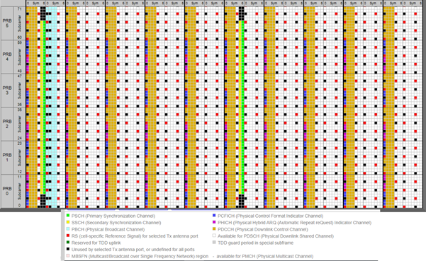
iv) For
UE camp on, basically as default its use 1.4MHZ where 6RB will utilised means (6*12)72
subcarrier where 10 subcarrier will reserved and will use for DTX purpose and
remaining 62 subcarrier will utilised for camp on process. 31 subcarrier for
primary synchronisation and remaining 31 subcarrier for secondary
synchronisation. But question is from where UE will start to read signal in 62
subcarrier?

v) Both
the FDD and TDD versions of LTE broadcast Synchronisation Signals in the
downlink direction. UE use the synchronisation primary and secondary signal in
TDD and FDD for the same purpose. In TDD achieve radio frame and slot
synchronisation but in FDD UE identify the central of channel bandwidth.
vi) But
question is how UE identify the central frequency? because it is call DC
subcarrier and here no power is required to sync with DC subcarrier, Once UE
sync with DC subcarrier it start to read PSS and SSS .
vii) PSS>>In
FDD, The Primary Synchronisation Signal (PSS) is broadcast twice during every
radio frame of time slots 0 and 10. PSS is broadcast using the central 62
subcarriers belonging to the last symbol of time slots 0 and 10.
In TDD, PSS is broadcast using the
central 62 subcarriers belonging to the third symbol of time slot 2 (subframe
1) and the third symbol of time slot 12 (subframe 6).
PSS
is used to:
a. Achieve subframe, slot and symbol
synchronisation in the time domain.
b. Identify the centre of the channel
bandwidth in the frequency domain.
c. Deduce a pointer towards 1 of 3
Physical layer Cell Identities (PCI).
d. PCI are organised into 168 groups of 3
so the Primary Synchronisation Signal identifies the position of the PCI within
the group but does not identify the group itself.
vii) SSS>>
In FDD, The Secondary Synchronisation Signal (SSS) is broadcast twice within
every radio frame. The two transmissions of the SSS are different so the UE can
detect which is the first and which is the second. SSS is broadcast using the
central 62 subcarriers belonging to the second to last symbol of time slots 0
and 10.
In TDD, SSS is broadcast using the central
62 subcarriers belonging to the last symbol of time slot 1 (subframe 0) and the
last symbol
Of time slot 11 (subframe 5)
SSS
is used to:
a. achieve radio frame synchronization
b. deduce a pointer towards 1 of 168
Physical layer Cell Identity (PCI) groups
c. allows the PCI to be deduced when
combined with the pointer from the PSS

Step-4) From the
list with successful result from Step-3), UE decode
MIBs for each and every candidate. With this procedure, now UE can make a list
of frequency, Physical Cell ID (PSC in case of WCDMA) and BW.
MasterInformationBlock ::= SEQUENCE {
dl-Bandwidth
ENUMERATED { n6, n15, n25, n50, n75, n100},
phich-Config
PHICH-Config,
systemFrameNumber
BIT STRING (SIZE (8)),
spare
BIT STRING (SIZE (10))
}
|
When the UE has
obtained the slot after decoding PSS, the best case scenario is the UE figured
out the Frame boundary(using SSS) in Subframe 0(which happens in slot0), in
which case it can immediately(in the slot1 of subframe 0) obtain the MIB info.
The worst case (or the only other) scenario is that it figures out in the
subframe 5, in which case it has to wait another 5 subframes for the Frame
start.
Once it obtained the Frame boundary, it makes sense to finish the MIB decoding in the subframe 0 itself, rather than waiting for another 5ms.
Once it obtained the Frame boundary, it makes sense to finish the MIB decoding in the subframe 0 itself, rather than waiting for another 5ms.
Step-5)
After decoding MIB,
UE has to decode PDCCH to read other system information blocks (SIBs).
PDCCH, PHICH and PCFICH share the resources in the control region of a
subframe. So to find the available resources for PDCCH, UE has to know the
PHICH configuration only, as PCFICH resources are fixed and known.
·
If CFI->2 it means 2 symbol are used
for PDCCH allocation.
·
PHICH = Location of PCFICH, Where it
will decode PCFICH. It will go with MIB.
·
PCFICH = PCFICH carry CFI -> Control
format indicator. CFI indicate how many OFDM symbol will use to carry PDCCH at
each subframe.
·
PDCCH= Its indicate which type of data
is going on PDSCH.
·
PDSCH=Here Read SIB
Based on
USIM information(Ex-PLMN) and the candidate table from the Step-4), can figure out which cell is the
real candidate cell to camp on and try decoding System Information and proceed
to registration process. Here it will verify USIM Stored PLMN with SIB1 PLMN
info.
No comments:
Post a Comment
If You have any concern you are free to message/comment me.