- What is component carrier?
- What is Carrier Aggregation?
- Types of LTE carrier aggregation
- Symmetric & Asymmetric CA in LTE
- Types of Component Carriers
- Carrier Aggregation – Cell Configuration
- Concept of Cross-Carrier Resource Scheduling
- Carrier Aggregation Activation/Deactivation

- It is of the most distinct features of 4G LTE-Advanced. Carrier aggregation allows expansion of effective bandwidth delivered to a user terminal through concurrent utilization of radio resources across multiple carriers. Multiple component carriers are aggregated to form a larger overall transmission bandwidth.
- CA supports wider bandwidths. Using CA, a spectrum of up to 5 Component Carriers (CC) can be aggregated up to a joint bandwidth of 100MHz. Rel–10 defines 5 possible deployment scenarios:
- Two co-located and overlaid (Fig 1.1) (lay another surface to cover) cells which provide nearly the same coverage and where both layers (cell) allocate different bandwidth parts within the same frequency band.
- CA is possible between both layers.
- Two co-located and overlaid (Fig 1.1) cells, in which only one layer provides sufficient coverage, while the other layer has smaller coverage due to higher path loss as both layers allocate bandwidth within different frequency bands.
- CA is possible between both layers.
- Two co-located cells (Fig 1.1) in which the antennas of the second cell are moved towards the cell boundaries of the first cell in order to enhance cell edge performance. The basic coverage is given by the first cell, while the second cell might not provide full coverage. Again, both cells have bandwidth in different frequency bands.
- CA is possible in regions where the coverage of both cells overlaps.
- Cell One provides basic macro coverage, while Cell Two has remote radio heads (RRH) (Scenario 4) or repeaters (Scenario 5) which provide additional capacity at hotspots within the coverage area of Cell One. Both cells transmit in different frequency bands.
- CA is possible from the RRH or repeater cells to the underlying macro Cell One.


- Some of you may be wondering what exactly carrier aggregation is but simply put, CA is a mechanism to increase channel bandwidth, or in other words, achieve higher data rates than standard LTE, as shown in Figure 1.2 Above.
- LTE as a technology supports up to 20MHz channel bandwidth, but with CA, the same can be enhanced to 100MHz as maximum five such channels (called component carriers), up to 20 MHz each, can be combined.

- Each aggregated carrier is referred to as a component carrier, CC. The component carrier can have a bandwidth of 1.4, 3, 5, 10, 15 or 20 MHz and a maximum of five component carriers can be aggregated and maximum aggregated bandwidth is 100 MHz.
- In FDD, The number of aggregated carriers can be different in DL and UL, see figure 1.3. Number of UL component carriers is always equal to or lower than the number of DL component carriers. The individual component carriers can also be of different bandwidths.
- Carrier aggregation is applicable to both FDD and TDD. in the case of TDD, the uplink-downlink sub frame configuration must be the same for all component carrier.
- For TDD the number of CCs as well as the bandwidths of each CC will normally be the same for DL and UL.
- Fig 1.3 illustrates two example of carrier aggregation-the first based upon 5 component carriers, and the second based upon 2 component carrier. The bandwidth of each component carrier is scenario dependent and does not have to be the maximum channel bandwidth of 20MHz.
- All component carriers belong to the same eNodeB and are synchronized on the air-interface. This means that a single set of timing advance command are used for all component carriers.
- Intra-band, Contiguous
- Intra-band ,non Contiguous
- Inter-band ,non-contiguous

- The Intra band scenario provide benefits in term of implementation effort. A single transceiver can transmit and receive multiple RF carrier when they are positioned within the same operating band.
- The inter-band scenario provides benefit in term of spectrum availability. An operator’s spectrum is likely to the distributed across multiple operating band rather than located within single band.
- Intraband Contiguous CA: when multiple CCs are adjacent to each other within the same band.
- Intraband Non-Contiguous CA: when multiple CCs within the same band are used in a non-contiguous manner (have a gap or gap between CC.)
- Interband Non-Contiguous CA: when multiple CCs are separated along the frequency band.
- With non-contiguous CA, data transmission occurs over multiple separated carriers across a large frequency range. As a result, the radio channel characteristics, such as propagation path loss and geometry (G-) factor. When carrier aggregation is used there are a number of serving cells, one for each component carrier. The coverage of the serving cells may differ, for example due to that CCs on different frequency bands will experience different path-loss, see figure 1.5


- symmetric carrier aggregation is defined as the case where there are equal number of component carriers for the downlink and uplink. In TDD downlink and uplink is always symmetric but in FDD ,the downlink and uplink can either be symmetric or not.
- In asymmetric case, the number of aggregated carrier can be different in DL/UL. However number of UL component carrier is always equal to or less than the number of DL component carriers. the individual component carrier can also be of different bandwidth.
- Primary Cell ( P-Cell )
- Secondary/Serving Cell ( S-Cell )
- The Primary cell is the Cell which is selected by the UE during cell search and used for RRC connection establishment . The measurement and mobility procedures are based on P-Cell. The P-Cell can never be de-activated .There is only one P-Cell per mobile device.
- The Secondary /Serving cells are those cells which are selected by the Network based on the UE capability and the position/Location of the UE which can serve the UE simultaneously along with the Primary Cell.
- The Secondary cells are Activated /De-activated by MAC Layer and get assigned to the mobile device by higher layers. There can be more than one S-Cell per mobile device.
- The SCCs are added and removed as required ,while the PCC is only changed at handover.
- Primary Serving Cell(PCell)
- Secondary Serving Cell(SCell)
- Each components carrier corresponds to a serving cell. The coverage of the serving cells may differ – both due to component carrier frequencies but also from power planning – which is useful for
- heterogeneous network planning. one of the serving cells is designed the primary cell, while the rest are known as secondary cells.
- The primary cell is the most important, and manages the CA configuration. the number of serving cells that can be configured depends on the aggregation capability of the UE.

- The RRC Connection is only handled by the Primary serving cell, served by the Primary component carrier(DL and UL PCC).it is also on the DL PCC that the UE receives NAS information, such as security parameters. In idle mode the UE listens to system information on the DL PCC. On the UL PCC PUCCH is sent.
- Random access procedure is performed over PCell.
- PDCCH/PDSCH/PUCCH/PUSCH can be transmitted.
- Measurements and mobility procedure are based on PCell
- Cannot be deactivated.
- Secondary Serving Cell is configured after connection establishment to provide additional radio resources.
- RACH procedure is not allowed in a secondary cell.
- PDCCH/PDSCH/PUSCH/can be transmitted(not PUCCH)
- MAC-layer based activation/deactivation is supported for SCell for UE battery saving.
- Can be cross-scheduled.
- Same- carrier scheduling
- Cross-Carrier scheduling

- Resources are scheduled on the same carrier as the grant is received.
- Separate PDCCH for each component carrier.
- Reusing LTE Release 8/9 PDCCH structure and DCI formats.
- Common PDCCH for multiple CCs.
- Reusing LTE Release 8/9 PDCCH structure.
- New 3-bit Carrier indicator field (CIF) added to Release 8 DCI.
- PCell shall be responsible for cross carrier scheduling of the secondary but no voice versa.
- PCell cannot to cross-scheduled; it is always scheduled through its own PDCCH.


- Step 1 – Configuration of Secondary Cells
- Step 2 – Activation/De-activation of Secondary Cells
CA Bandwidth Class
| CA Bandwidth Class | Aggregated Transmission Bandwidth configuration | Number of contiguous Componenet Carriers |
|---|---|---|
| A | NRB,agg ≤ 100 | 1 |
| B | 25 < NRB,agg ≤ 100 | 2 |
| C | 100 < NRB,agg ≤ 200 | 2 |
| D | 200 < NRB,agg ≤ 300 | 3 |
| E | 300 < NRB,agg ≤ 400 | 4 |
| F | 400 < NRB,agg ≤ 500 | 5 |
| I | 700 < NRB,agg ≤ 800 | 8 |
Intra-band contiguous channel spacing
For Intra-band contiguous we have to take in to account the nominal channel spacing. For intra-band contiguous carrier aggregation with two or more component carriers, the nominal channel spacing between two adjacent E-UTRA component carriers is defined as the following:
Intra-band contiguous channel spacing
where BW Channel(1) and BWChannel(2) are the channel bandwidths of the two respective E-UTRA component carriers.
PCC – Primary Component Carrier (PCell)
SCC – Secondary Component Carrier (SCell)For example: 2CA band 40C
If we are planning to set a PCell of bandwidth 20 MHz(BW1) and a SCell of bandwidth 20 MHz(BW2) then the nominal spacing will be calculated as follows,
Nominal Channel Spacing = FLOOR.MATH((20+20-0.1*ABS(20-20))/0.6)*0.3
= FLOOR.MATH((40+0.1*0)/0.6)*0.3
= FLOOR.MATH(40/0.6)*0.3
= FLOOR.MATH(66.6666667)*0.3
Nominal Channel Spacing = (66)*0.3 => 19.8 MHz
NOTE: (You can put the line “FLOOR.MATH((20+20-0.1*ABS(20-20))/0.6)*0.3” directly into Excel and it should give you 19.8).
Which means for Intra-band contiguous the Channel Spacing should be a multiple of 300 KHz and equal to (or) less than Nominal Channel Spacing,Channel Spacing < Nominal Channel Spacing
Channel Spacing = ((BW1+BW2)/2).
If we take the PCC EARFCN=39000, Frequency=2335, Bandwidth=20 MHz then the SCC is calculated as,
SCC EARFCN = PCC EARFCN + 19.8 * 10
= 39000 + 198
= 39198
SCC EARFCN=39198, Frequency=2354.8, Bandwidth=20 MHzThe Nominal Channel Spacing is 19.8 MHz (2335 – 2354.8) which is less than or equal to Channel Spacing of 19.8 MHz. Only when this condition is satisfied it is treated as Intra-band contiguous.
For intra-band non-contiguous carrier aggregation the channel spacing between two E-UTRA component carriers in different sub-blocks shall be larger than the nominal channel spacing. (ie) The combination is considered as 40A-40A,
Channel Spacing > Nominal Channel Spacing
radioResourceConfigCommonSCell: This is a big structure of IEs which is mandatory at the time of SCell Addition and shouldn’t be present if the concerned SCell is being Modified.

MAC CE - SCell Activation/Deactivation
The purpose and the mechanism of NR SCell Activation/Deactivation is same as LTE SCell Activation/Deactivation. It is used to activate or deactivate data transmission for SCell while it is in Carrier Aggregation as illustrated below. That is, setting up carrier aggregation is done by RRC process but once RRC job is done, the real swich on/off of data transmission is done by this MAC CE.


MAC CE - Activation/Deactivation MAC Control Element
Refer to 36.321 6.1.3.8 Activation/Deactivation MAC Control Element if you want to have formal description. The field structure is as shown below.
< 36.321 Rel 10,11,12 - Figure 6.1.3.8-1: Activation/Deactivation MAC control element >

From Rel 13, UE Category 17 is added. Based Category 17, we can achieve 32 CC Carrier Aggregation and 25 Gbps. To support 32 CC (31 SCC), a new Activation/Deactivation MAC CE is added as shown below.
< 36.321 Rel 13 - Figure 6.1.3.8-2: Activation/Deactivation MAC control element of four octets >

Now the question is to figure out what does C1, C2, C3 etc mean ? Does it automatically mean C1 = SCC1, C2 = SCC2 etc ?
No.. the mapping between C1, C2,..,C7 and SCC1,SCC2,...,SCC7 is defined in RRC Connection Reconfig message. One example is as follows : (In example, sCellIndex-r10 for SCC1 (the first SCC) is set to be 2. It means C2 field in MAC CE is mapped to SCC1. Therefore, in this case 00000100 means that the first SCC shall be activated. This mean that absolution bit position in MAC CE does not specify whether it is for SCC1 or SCC2 etc. The meaning of each bit in MAC is indicated by RRC message. It means what is important is the matching between sCellIndex-r10 and MAC CE bit position. I hope following illustration would sound clearer to you.

ollowing is an example of RRC Connection Reconfiguration message to add SCC1.
rrcConnectionReconfiguration-r8
radioResourceConfigDedicated
physicalConfigDedicated
pucch-ConfigDedicated-v1020
pucch-Format-r10: channelSelection-r10 (1)
channelSelection-r10
n1PUCCH-AN-CS-r10: setup (1)
setup
n1PUCCH-AN-CS-List-r10: 2 items
Item 0
N1PUCCH-AN-CS-r10: 4 items
Item 0
N1PUCCH-AN-CS-r10 item: 361
Item 1
N1PUCCH-AN-CS-r10 item: 362
Item 2
N1PUCCH-AN-CS-r10 item: 363
Item 3
N1PUCCH-AN-CS-r10 item: 364
Item 1
N1PUCCH-AN-CS-r10: 4 items
Item 0
N1PUCCH-AN-CS-r10 item: 365
Item 1
N1PUCCH-AN-CS-r10 item: 366
Item 2
N1PUCCH-AN-CS-r10 item: 367
Item 3
N1PUCCH-AN-CS-r10 item: 368
nonCriticalExtension
nonCriticalExtension
nonCriticalExtension
sCellToAddModList-r10: 1 item
Item 0
SCellToAddMod-r10
sCellIndex-r10: 2
cellIdentification-r10
physCellId-r10: 1
dl-CarrierFreq-r10: 3100
radioResourceConfigCommonSCell-r10
nonUL-Configuration-r10
dl-Bandwidth-r10: n50 (3)
antennaInfoCommon-r10
antennaPortsCount: an1 (0)
phich-Config-r10
phich-Duration: normal (0)
phich-Resource: one (2)
pdsch-ConfigCommon-r10
referenceSignalPower: 18dBm
p-b: 0
radioResourceConfigDedicatedSCell-r10
physicalConfigDedicatedSCell-r10
nonUL-Configuration-r10
antennaInfo-r10
transmissionMode-r10: tm1 (0)
ue-TransmitAntennaSelection: release (0)
release: NULL
pdsch-ConfigDedicated-r10
p-a: dB0 (4)
ul-Configuration-r10
cqi-ReportConfigSCell-r10
nomPDSCH-RS-EPRE-Offset-r10: 0dB (0)
cqi-ReportPeriodicSCell-r10: release
- PCell always have both Uplink(UL) and Downlink(DL). Scell always have DL (While activated) but may or may not have UL.
- PCell is always activated whereas SCell has to be activated or deactivated using MAC-CE.
- UE does not required to acquire System Information and decode Paging from SCell.
- For Scell SI is passed to UE while adding the Scell.
- When an Scell is added using RRC Connection Reconfiguration Message it remains in the deactivated state till it is activated using MAC-CE.
- If Scell activation/deactivation MAC-CE is received on Subframe n the Scell is activated/deactivated on Subframe n+24 or n+34.(TS 36.133 Section 7.7.2)
- When sCellDeactivationTimer expires then Scell is deactivated.
- Once Scell is deactivated
- PDCCH on Scell and PDCCH for Scell is not monitored.
- PUSCH is not transmitted and PDSCH is not received.
- The SRS is not transmitted.
- The CQI/PMI/RI for Scell is not reported.
Activation/Deactivation MAC-CE:
- The MAC-CE can activate and deactivate Scell(s) which is already configured using RRC Connection Reconfiguration Meassage.
- Control Element is identified by a MAC PDU subheader with LCID.
.
Index | LCID values |
11011 | Activation/Deactivation |
- fixed size and consists of a single octet containing seven C-fields and one R-field.
 |
| Activation/Deactivation MAC control element |
-
Pcell and Scell Concepts:
- Pcell can be changed using RRC Connection Reconfiguration With MobilityControlInfo i.e. Handover.
- Scell can be changed using RRC Connection Reconfiguration message.
- During Radio Link Failure, the Scell is release first before initiating RRC Connection Re-establishment procedure.
- On receiving Handover Command i.e. RRC Connection Reconfiguration With MobilityControlInfo, UE deactivates the Scell, if configured.
- TTI Bundling is not supported when configured with one or more Scell with Configured Uplink.
- The RSRP and RSRQ measurement for Pcell shall follow time domain measurement resource restriction in accordance with measSubframePatternPCell, if configured.
Procedure | Pcell | Scell |
Radio Link Monitoring | Y | N |
System Information Acquisition | Y | N |
Random Access Procedure | Y | N |
Time Alignment | Y | N |
SPS | Y | N |
Connected Mode DRX | Y | Y |
Paging | Y | N |
NAS Mobility Information | Y | N |
Data Transmission | Y | Y |
S-measure Criteria | Y | N |
Power Control | Y | Y |
Link Adaptation | Y | Y |
Pathloss Meaurement | Y | Y= when pathloss reference=Scell N= when pathloss reference=Pcell |
Channel | Pcell | Scell |
PDCCH | Y | Y - No Cross Carrier Scheduling N - Cross Carrier Scheduling (UE does not look at PDCCH when CCS but eNodeB might be transmitting PDCCH.) |
PDSCH | Y | Y |
PUCCH | Y | N |
PUSCH | Y | Y |
PRACH | Y | N |
SRS | Y | Y |
PBCH | Y | N - UE does not look at PBCH But eNodeB might be transmitting it. |
PSS/SSS | Y | N - UE does not look at PSS/SSS but to get timing information eNodeB might be transmitting PSS/SSS. |
PCFICH | Y | Y - No Cross Carrier Scheduling N - Cross Carrier Scheduling (UE does not look at PCFICH when CCS but eNodeB might be transmitting PCFICH.) |
PHICH | Y | Y - No Cross Carrier Scheduling N - Cross Carrier Scheduling (UE does not look at PHICH when CCS but eNodeB might be transmitting PHICH.) |
What are new for the new DCI format : Format 2B and 2C ? I created a comparative table for you to see the difference between these new format and the existing field.
Format 2 (Rel 10) | Format 2A (Rel 10) | Format 2B (Rel 10) | Format 2C (Rel 10) |
Carrier indicator | Carrier indicator | Carrier indicator | Carrier indicator |
RA header | RA header | RA header | RA header |
Resource block assignment | Resource block assignment | Resource block assignment | Resource block assignment |
TPC command for PUCCH | TPC command for PUCCH | TPC command for PUCCH | TPC command for PUCCH |
Downlink Assignment Index(TDD only) | Downlink Assignment Index(TDD only) | Downlink Assignment Index(TDD only) | Downlink Assignment Index(TDD only) |
HARQ process number | HARQ process number | HARQ process number | HARQ process number |
Scrambling identity | Antenna ports Scrambling identity Number of Layers | ||
SRS request(TDD Only) | SRS request(TDD Only) | ||
TB to CW flag | TB to CW flag | TB to CW flag | TB to CW flag |
| MCS for TB1 | MCS for TB1 | MCS for TB1 | MCS for TB1 |
| NDI for TB1 | NDI for TB1 | NDI for TB1 | NDI for TB1 |
| RV for TB1 | RV for TB1 | RV for TB1 | RV for TB1 |
| MCS for TB2 | MCS for TB2 | MCS for TB2 | MCS for TB2 |
| NDI for TB2 | NDI for TB2 | NDI for TB2 | NDI for TB2 |
| RV for TB2 | RV for TB2 | RV for TB2 | RV for TB2 |
Precoding information | Precoding information | Precoding information | Precoding information |
The totally new DCI introduced in Release 10, Format 4, carries the information as shown below.
Format 4 |
Carrier indicator (0 or 3 bits) |
Resource block assignment |
TPC command for scheduled PUSCH (2 bits) |
Cyclic shift for DM RS and OCC index (3 bits) |
Downlink Assignment Index (DAI) (2 bits) |
CSI request (1 or 2 bits) |
SRS request (2 bits) |
Resource allocation type (1 bit) |
MCS and RV for TB1 (5 bits) |
NDI for TB1 (1 bit) |
MCS and RV for TB2 (5 bits) |
NDI for TB2 (1 bit) |
Precoding information and number of layers |
< DCI 1 Examples > ----------------------------------------------------------------------------------------
Example 1 > DCI Format 1 - 20 Mhz, Value = 0x0FC00005DC40
Field | Value | Value (Binary) |
| CarrierIndicator | 0 (Dec) | 000 |
RA header | RAType0 | 0 |
Resource block assignment | 1111110000000000000000000 | 1111110000000000000000000 |
MCS | 23 (Dec) | 10111 |
HARQ process number | 3 (Dec) | 011 |
NDI | 1 | 1 |
RV | 0 (Dec) | 00 |
TPC | 01 | 01 |
Example 2 > DCI Format 1 - 20 Mhz, Value = 0x2FC00005DC00
Field | Value | Value (Binary) |
| CarrierIndicator | 1 (Dec) | 001 |
RA header | RAType0 | 0 |
Resource block assignment | 1111110000000000000000000 | 1111110000000000000000000 |
MCS | 23 (Dec) | 10111 |
HARQ process number | 3 (Dec) | 011 |
NDI | 1 | 1 |
RV | 0 (Dec) | 00 |
TPC | 0 (Dec) | 00 |
< DCI 2A Examples > ----------------------------------------------------------------------------------------
Example 1 > DCI Format 2A - 20 Mhz, Value = 0x7E000010BCBC
Field | Value | Value (Binary) |
RA header | RAType0 | 0 |
Resource block assignment | 1111110000000000000000000 | 1111110000000000000000000 |
TPC command for PUCCH | 01 | 01 |
HARQ process number | 0 (Dec) | 000 |
TB to CW flag | 0 | 0 |
MCS for TB1 | 23 (Dec) | 10111 |
NDI for TB1 | 1 | 0 |
RV for TB1 | 0 (Dec) | 00 |
MCS for TB2 | 23 (Dec) | 10111 |
NDI for TB2 | 1 | 1 |
RV for TB2 | 0 (Dec) | 00 |
< DCI 2C Examples > ----------------------------------------------------------------------------------------
Example 1 > DCI Format 2C - 10 Mhz, Value = 0x7FFFDC3435C0
Field | Value | Value (Binary) |
RA header | RAType0 | 0 |
Resource block assignment | 11111111111111111 | 11111111111111111 |
TPC command for PUCCH | 01 | 01 |
HARQ process number | 6 (Dec) | 110 |
Ports-SCID-Number of Layers | 0 | 000 |
MCS for TB1 | 26 (Dec) | 11010 |
NDI for TB1 | 0 | 0 |
RV for TB1 | 0 (Dec) | 00 |
MCS for TB2 | 26 (Dec) | 11010 |
NDI for TB2 | 1 | 1 |
RV for TB2 | 3 (Dec) | 11 |
- Downlink Scheduling or Uplink Grant information of One Component Carrier(CC) can be carried by the PDCCH of another Component Carrier(CC).
- 3 bit CIF field indicates target CC.
- Pcell shall always be scheduled by Pcell only.
- Scell can be cross scheduled by Pcell or by other Scell.
- UE indicates whether it supports CCS or not.
- Cross Carrier Scheduling is not applicable for PDCCH order. It is transmitted on Pcell.
- CCS is applicable for aperiodic SRS transmission.


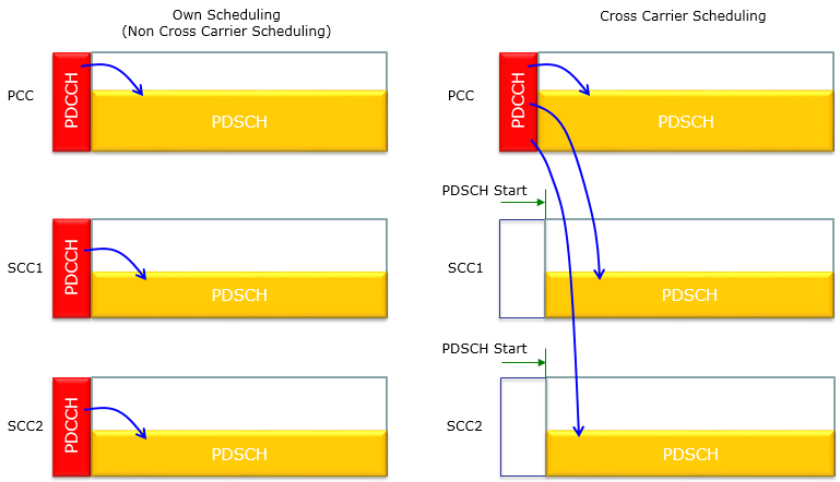
Who Schedule Each Component Carriers ?
When you have multiple Carriers in Carrier Aggregation, you naturally have a question. That is, who (which carrier) will be schedule resource allocation for each sub carriers ?
There are two types of method we can think of as illustrated below. In one case (Own Scheduling), each component carrier schedules for its own carrier. In the other case (Cross Carrier Scheduling), Primary Compnent Cell (or any specified serving cell) schedules the resource for all the component carriers.
Then you would have another question. How UE knows whether eNB is doing "cross carrier scheduling" or "non cross carrier scheduling" ?
This information is informed to UE via Higher Layer Signaling (RRC Message) as shown below.
< Own (Non Cross Carrier) Scheduling >
If Network (eNB) decided to do Own(Non-Cross carrier) Scheduling, it notifies UE using RRC message as shown below.
rrcConnectionReconfiguration
rrc-TransactionIdentifier: 0
criticalExtensions: c1 (0)
c1: rrcConnectionReconfiguration-r8 (0)
rrcConnectionReconfiguration-r8
radioResourceConfigDedicated
physicalConfigDedicated
nonCriticalExtension
lateNonCriticalExtension: <MISSING>
nonCriticalExtension
nonCriticalExtension
sCellToAddModList-r10: 1 item
Item 0
SCellToAddMod-r10
sCellIndex-r10: 1
radioResourceConfigDedicatedSCell-r10
physicalConfigDedicatedSCell-r10
nonUL-Configuration-r10
crossCarrierSchedulingConfig-r10
schedulingCellInfo-r10: own-r10 (0)
own-r10
.... ..0. cif-Presence-r10: False
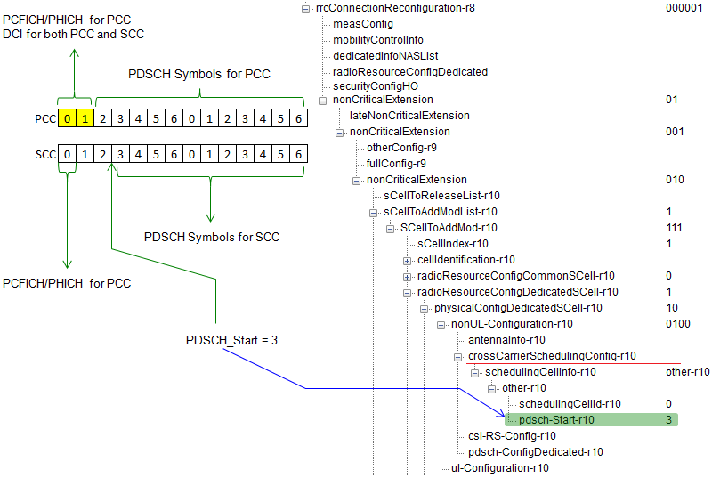
If Network (eNB) decided to do Cross carrier Scheduling, it notifies UE using RRC message as shown below.
rrcConnectionReconfiguration
rrc-TransactionIdentifier: 0
criticalExtensions: c1 (0)
c1: rrcConnectionReconfiguration-r8 (0)
rrcConnectionReconfiguration-r8
radioResourceConfigDedicated
physicalConfigDedicated
nonCriticalExtension
lateNonCriticalExtension: <MISSING>
nonCriticalExtension
nonCriticalExtension
sCellToAddModList-r10: 1 item
Item 0
SCellToAddMod-r10
sCellIndex-r10: 1
radioResourceConfigDedicatedSCell-r10
physicalConfigDedicatedSCell-r10
nonUL-Configuration-r10
crossCarrierSchedulingConfig-r10
schedulingCellInfo-r10: other-r10 (1)
other-r10
schedulingCellId-r10: 0
pdsch-Start-r10: 3


- Support for carrier aggregation feature requires enhancement to the 3GPP LTE Release 8 & 9 physical, MAC, and RRC protocol layers. To an LTE Release 8 terminal, each component carrier will appear as an LTE carrier, while an LTE-Advanced terminal can use the total aggregated bandwidth.
What is criteria to activate Secondary cell???
ReplyDeleteGautam ji, UE send measurement report to the eNB. Which S-Cell has strongest RSRP/RSRQ, Network will activate that Cell as S_Cell.
DeleteSomit Mishra-
DeleteHow the Uplink HARQ Ack/Nack function works for DL in carrier aggregation?
ReplyDelete